
Method and system for reducing potential interference in an impulse radio

a technology of impulse radio and interference reduction, applied in the field of wireless communication, can solve the problems of serious degraded impulse amplitude accuracy, corrupt impulse amplitude, and easy interference of relatively broad and relatively narrow bands by impulse receivers, and achieve the effect of reducing interferen

Inactive Publication Date: 2005-07-05
ALEREON
View PDF39 Cites 134 Cited by
  • Summary
  • Abstract
  • Description
  • Claims
  • Application Information

AI Technical Summary

Benefits of technology

[0018]The present invention has the feature of canceling or reducing interference in an impulse radio receiver adapted to receive an impulse signal, where the interference can have an amplitude many magnitudes greater than an impulse signal amplitude. A related feature of the present invention is to cancel multiple interference signals concurrently received with an impulse signal.
[0020]By reducing interference in an impulse radio receiver, the present invention has the advantage of improving the signal-to-interference (S / I) level in the impulse radio.
[0022]The present invention has the advantage of reducing relatively high duty cycle interference in an impulse radio, using techniques compatible with a low duty cycle architecture of the impulse radio, and thus, without using circuit elements more generally associated with high duty cycle radios.

Problems solved by technology

Interference can seriously degrade impulse amplitude accuracy.
Such interference can include interference having a relatively broadband frequency characteristic, such as random or broadband noise.
The impulse receiver is susceptible to both the relatively broadband and the relatively narrow band interference.
Therefore, the relatively narrow band interference can corrupt the impulse amplitudes.
In such instances, the randomizing codes may provide insufficient attenuation of the interference.
Therefore, the random noise component can cause large relative fluctuations in the impulse amplitude, thereby corrupting the impulse amplitude accuracy.
It is undesirable to introduce the above mentioned circuit elements into an impulse radio to cancel the relatively high duty cycle interference because of impulse radio cost, size, and power constraints.
Moreover, the impulse radio architecture may not be compatible with such circuit elements.

Method used


Image

  • Method and system for reducing potential interference in an impulse radio
  • Method and system for reducing potential interference in an impulse radio
  • Method and system for reducing potential interference in an impulse radio

Examples


Embodiment Construction

Table of Contents

[0091]I. Impulse Radio Basics[0092]A. Waveforms[0093]B. A Pulse Train[0094]C. Coding for Energy Smoothing and Channelization[0095]D. Modulation[0096]E. Reception and Demodulation[0097]F. Interference Resistance[0098]G. Processing Gain[0099]H. Capacity[0100]I. Multipath and Propagation[0101]J. Distance Measurement[0102]K. Example Transceiver Implementation[0103]1. Transmitter[0104]2. Receiver[0105]II. Preferred Embodiments[0106]A. Interference Canceling Environment[0107]1. Interference-free Waveforms[0108](a) Terminology[0109](b) Waveform Discussion[0110]2. Problem Description[0111]3. Solution[0112](a) Interference Canceling Characterized in the Frequency Domain[0113]4. Simultaneous Canceling of Two Narrow band Interference Components Using a Single Nulling Sample[0114]5. Multipath Avoidance[0115]B. General Purpose Architectural Embodiment for Impulse Radio[0116]1. Overview[0117]2. RF Sampling Subsystem[0118]3. Timing Subsystem[0119]4. Control Subsystem[0120]5. Baseb...


PUM


Abstract

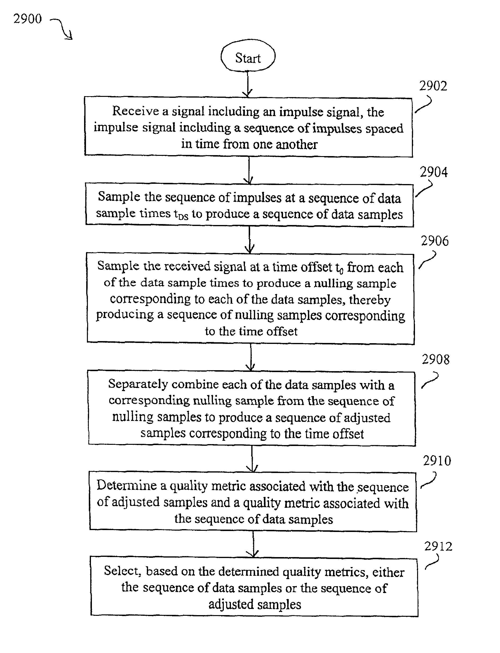
Potential interference is reduced in an impulse radio. A signal including an impulse signal and potential interference is received by the impulse radio. The impulse signal includes a sequence of impulses. The sequence of impulses of the received signal is sampled at a sequence of data sample times to produce a sequence of data samples. The received signal is also sampled at a plurality of time offsets from each of the data sample times to produce a plurality of nulling samples corresponding to each of the data samples. A separate sequence of nulling samples for each of the time offsets is thereby produced. Each of the data samples is then separately combined with a corresponding nulling sample from each of the separate sequences of nulling samples to produce a separate sequence of adjusted samples corresponding to each of the time offsets. A separate quality metric, representative of a signal-to-interference level, is then determined for each of the separate sequences of adjusted samples. A preferred sequence of samples is selected for further signal processing based on the determined quality metrics. Alternatively or additionally, one of the plurality of time offsets is selected as the preferred time offset based on the determined quality metrics.

Description

CROSS-REFERENCE TO RELATED APPLICATIONS[0001]This application is a Continuation-In-Part (CIP) of U.S. patent application Ser. No. 09 / 689,702, filed Oct. 13, 2000, and entitled “Method and System for Canceling Interference in an Impulse Radio.”BACKGROUND OF THE INVENTION[0002]1. Field of the Invention[0003]The present invention generally relates to wireless communications, and more specifically, to a method and system for reducing interference in a wireless receiver.[0004]2. Related Art[0005]An impulse radio system includes an impulse transmitter for transmitting an impulse signal and an impulse receiver spaced from the transmitter for receiving the impulse signal. The impulse signal comprises a train of low power impulses having an ultra-wideband and / or medium wide band frequency characteristic. The impulse receiver samples the low power impulses in the train of impulses to produce a corresponding train of received impulse samples (also referred to as data samples), each having an i...

Claims


Application Information

Patent Timeline
IPC IPC(8): H04B1/69H04B1/7163H04B1/719
CPCH04B1/719H04B1/71637H04B2001/6908
Inventor RICHARDS, JAMES L.BRETHOUR, VERNON R.
Owner ALEREON
Learn More