Zone detection locator

a technology of locators and zones, applied in the direction of instruments, electric signalling details, signalling systems, etc., can solve the problems of increasing deployment and maintenance costs, reducing overall system reliability, and high total cost of deploying and maintaining such systems, so as to reduce the requirements of computer signal processing

Inactive Publication Date: 2005-07-12
EXCELIS INC
View PDF26 Cites 41 Cited by
  • Summary
  • Abstract
  • Description
  • Claims
  • Application Information

AI Technical Summary

Benefits of technology

[0011]Therefore, in light of the above, and for other reasons that will become apparent when the invention is fully described, an object of the p

Problems solved by technology

Further, the ID tags and interrogators must both be capable of receiving and processing signals as well as generating and transmitting signals, thus increasing deployment and maintenance costs and decreasing overall system reliability due to increased complexity.
However, the total cost of deploying and maintaining such systems remains high and the ability of such systems to simultaneously track large numbers of ID tags, or to timely track individual ID tags within a large pool of deployed ID tags remains limited.
Further, such systems still rely upon a distributed network of signal processing receivers that have a fixed signal processing capacity and, therefore, are not capable of supporting large swells in ID tag movements.
Conventional tracking systems are typically limited with respect to the number of ID tags that can be simultaneously supported.
Such limitations are typically due to the heavy communication traffic and/or signal processing associated with continually polling and/or processing signals received from each individual tag in the system.
To handle high loads, complex, high-speed signal processing equipment is required, thus increasing system deployment costs, increasing system failures, and hence increasing down-time a

Method used


Image

  • Zone detection locator
  • Zone detection locator
  • Zone detection locator

Examples


Embodiment Construction

[0033]Preferred embodiments according to the present invention are described below with reference to the above drawings, in which like reference numerals designate like components.

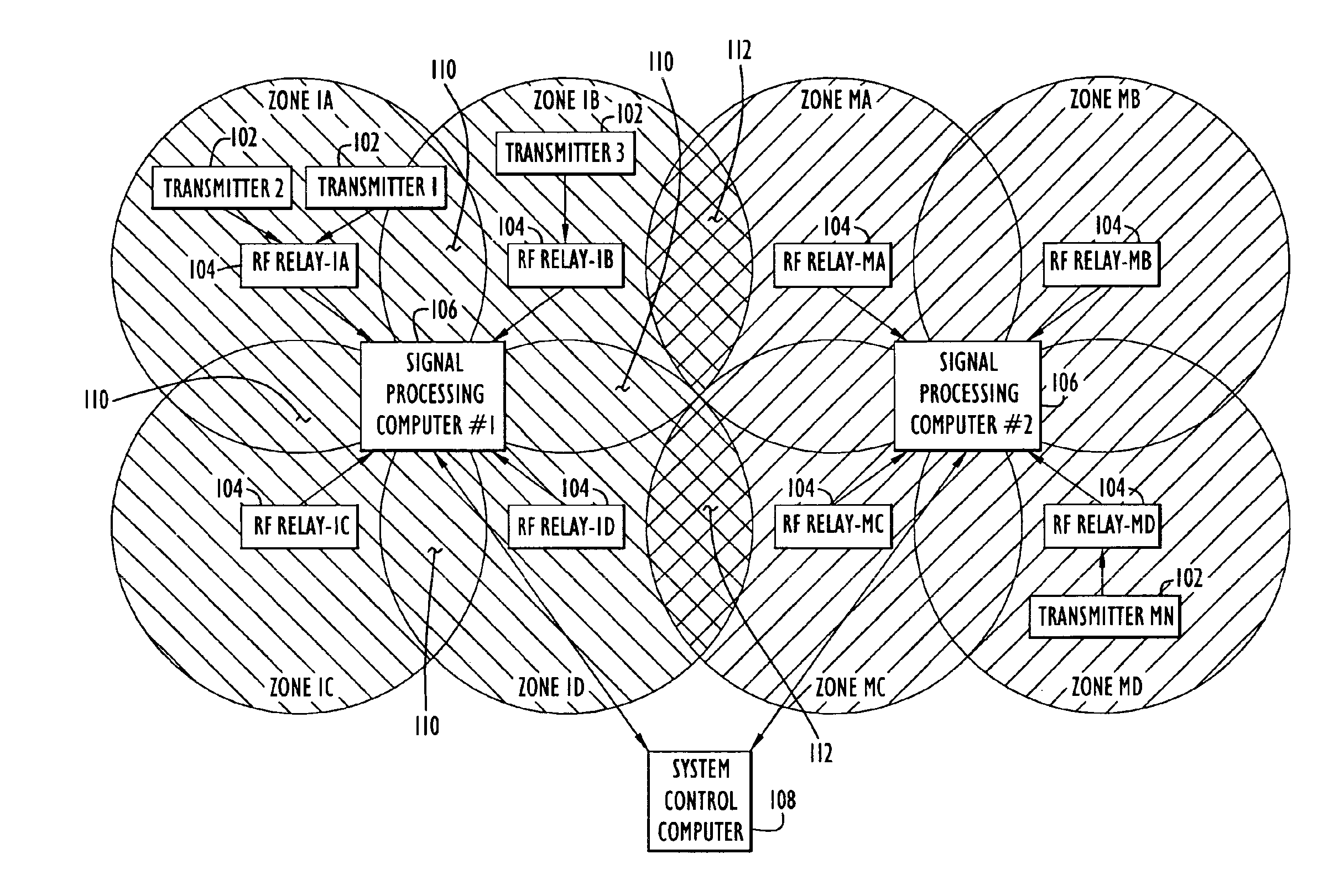
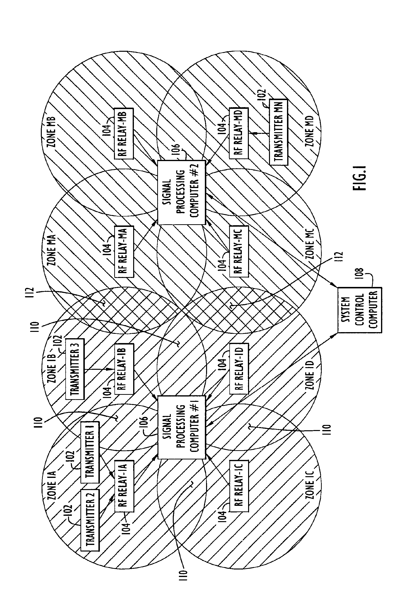
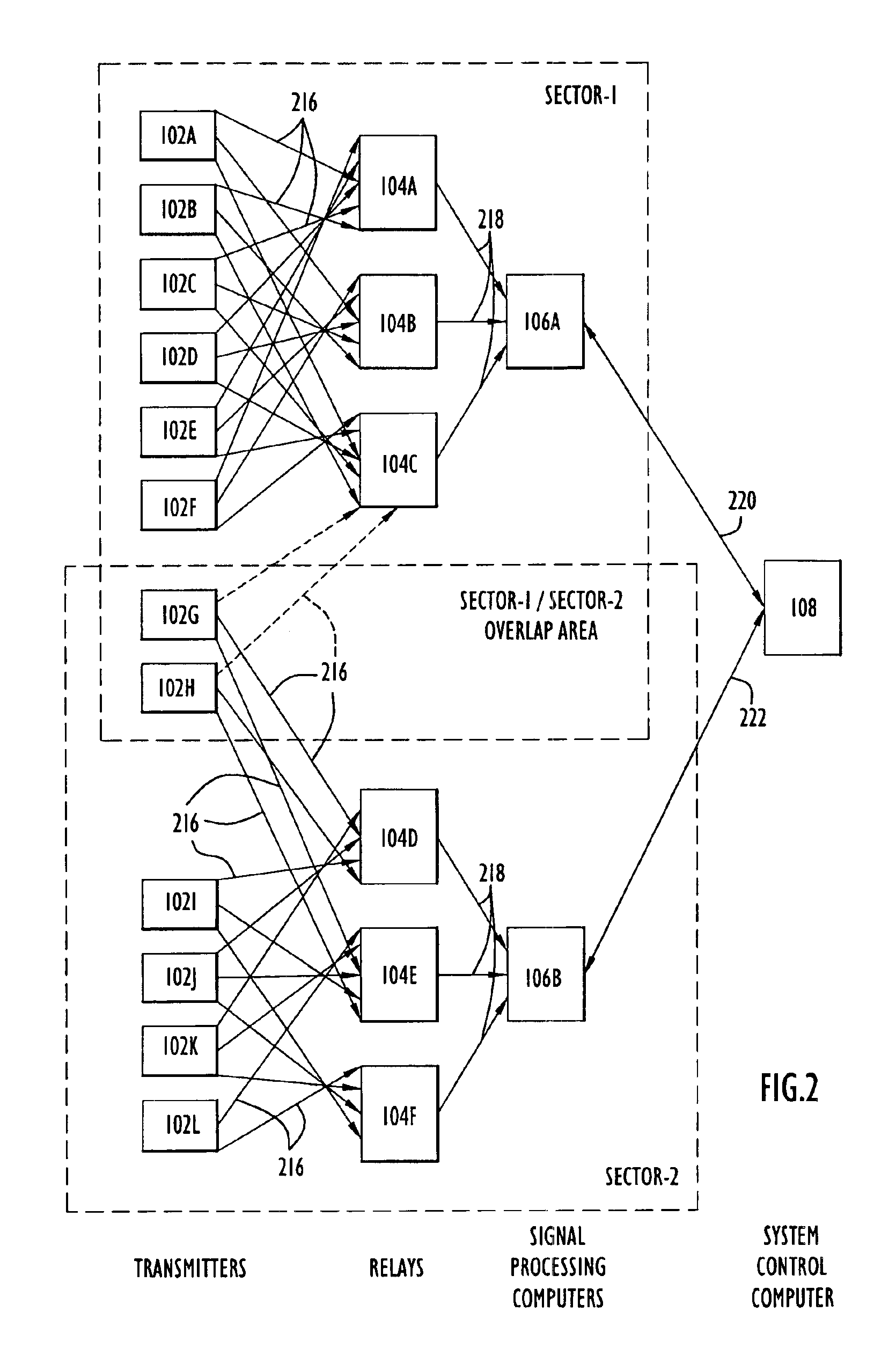
[0034]FIG. 1 presents a representative system architecture for a zone detection system that includes transportable, low-power, battery operated pseudonoise spread spectrum radio frequency (RF) transmitters 102, and distributed low-cost RF signal relays (or RF-relays)104, that receive signals from the respective transmitters and relay the received signals to one or more signal processing computers 106. The system further includes a system controller 108 that is used to integrate data received from the respective signal processing computers 106 and to provide a common user interface for the zone detection system.

[0035]For example, an RF transmitter 102 can be embedded in a wristband or badge and attached by a guardian to a child in a shopping mall. Should the child and guardian become separated, the location...


PUM


Abstract

A method and apparatus for a zone detection system in which assets and personnel to be monitored are assigned a transmitter that emits a transmitter signal that includes a common code and a unique code. Processing requirements associated with restricted zone monitoring are reduced by scanning received signals for the single common code or a relatively small number of common codes. Processing requirements associated with locating an individual transmitter are reduced by scanning for a single transmitter signal. Transmitter signals are relayed by sub-sector RF-relays to a centralized sector signal processing computer. One or more signal processing computers interface with a system controller that supports a centralized user interface configurable to manage one or more sectors. CDMA matched filter techniques, power signature maps, and two-dimensional/three-dimensional convolution techniques are used to efficiently detect signals and to refine the estimated location a specific transmitter or a group of transmitters.

Description

CROSS-REFERENCE TO RELATED APPLICATIONS[0001]This application claims priority from U.S. Provisional Patent Application Ser. No. 60 / 417,654, entitled “Zone Detection Locator” and filed Oct. 11, 2002, the disclosure of which is incorporated herein by reference in its entirety.BACKGROUND OF THE INVENTION[0002]1. Field of the Invention[0003]The present invention pertains to mobile transmitter location and tracking systems. In particular, the present invention pertains to a centrally controlled tracking system used to locate and / or track material assets and / or personnel within a monitored area of control.[0004]2. Description of the Related Art[0005]The need to locate and track material assets and / or individuals within a predetermined monitored area of control is evident from a wide range of conventional mobile asset and / or personnel tracking systems. Typically in these systems, the asset or individual to be tracked is assigned a mobile, signal-emitting identification (ID) tag, embedded w...

Claims


Application Information

Patent Timeline
IPC IPC(8): G01S5/02G06K7/00G06K17/00G01S19/11
CPCG01S5/02G06K7/0008G06K7/10079G06K19/07758G08B13/2462G06K2017/0045G01S2205/09G01S5/0295
Inventor LAND, THOMAS
Owner EXCELIS INC
Why Eureka
Try Eureka