Optical fiber having reduced viscosity mismatch

a technology of optical fiber and viscosity mismatch, applied in the field of optical fiber, can solve the problems of increased transmission loss, low chlorine level used, and mismatch between pure silica core glass and doped silica cladding glass

Inactive Publication Date: 2005-07-12
CORNING INC
View PDF8 Cites 78 Cited by
  • Summary
  • Abstract
  • Description
  • Claims
  • Application Information

AI Technical Summary

Benefits of technology

[0009]In one embodiment of the present invention an optical fiber is disclosed having a core region having a refractive index n1, a relative refractive index %Δ1, and a glass transition temperature Tg1; a first cladding segment disposed about and in contact with the outer periphery of the core region, wherein the first cladding segment has a refractive index n2, a relative refractive index % Δ2, and a glass transition temperature Tg2; and wherein the core region is doped with Cl and F, and the Cl and F are in an amount by wt. % effective to yield a difference between Tg1 and Tg2 of less than about 200° C.

Problems solved by technology

That is, when a dopant such as F is added to a silica glass cladding region, the viscosity of the cladding region is lowered, resulting in a viscosity mismatch between the pure silica core glass and the doped silica cladding glass.
Residual stress, that is, stress that has been frozen into the fiber upon cooling from the draw temperature, is one cause of increased transmission loss.
However, the generally low level of chlorine that has been used, about 1 wt.
% or less, has by itself been insufficient to adequately match the viscosity of the core region to the viscosity of the cladding region.
Since Cl alone is not an effective modifier of viscosity, large amounts of Cl are required to closely match the core viscosity to the cladding viscosity.
However, the high volatility of Cl limits the amount of Cl that can be added to the core region in some optical fiber manufacturing methods, such as those that employ outside vapor deposition (OVD) or vapor axial deposition (VAD).
The inability to dope an adequate amount of Cl into the core region has limited the effectiveness of this approach, thus very slow draw speeds and high draw furnace temperatures are still typically required to avoid draw-induced defects such as voids in the glass, excess residual stress, and increased optical fiber attenuation in the manufacture of silica core optical fiber.

Method used


Image

  • Optical fiber having reduced viscosity mismatch
  • Optical fiber having reduced viscosity mismatch
  • Optical fiber having reduced viscosity mismatch

Examples


example 1

[0069]The following specific example illustrates the manner in which the method of the present embodiment can be employed to produce a single-mode optical waveguide fiber having a silica core doped with Cl and F, and a fluorine-doped silica cladding. An integral handle 38 of the type disclosed in U.S. Pat. No. 4,289,522 is employed. An alumina mandrel 36 was inserted into handle 38, the central region where soot particles are ultimately deposited being tapered in diameter from about 5.5 mm to 6.5 mm.

[0070]Liquid SiCl4 was maintained at 37° C. in a container. Burner 42 traversed a 49 cm section of mandrel 36 in 25 seconds. An acetylene torch supported on burner 42 was first employed to deposit carbon particles on mandrel 36 during one burner pass. During the next 30 minutes, oxygen was flowed at a rate of 0.05 slpm through a SiCl4 container, the resultant mixture flowing to the burner. The resultant fine soot stream formed a layer of silica soot having a thickness of about 1 mm. Duri...

example 2

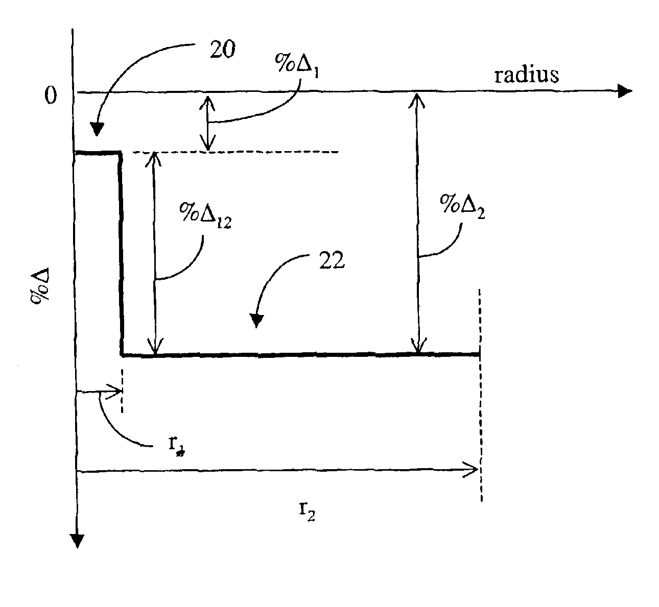
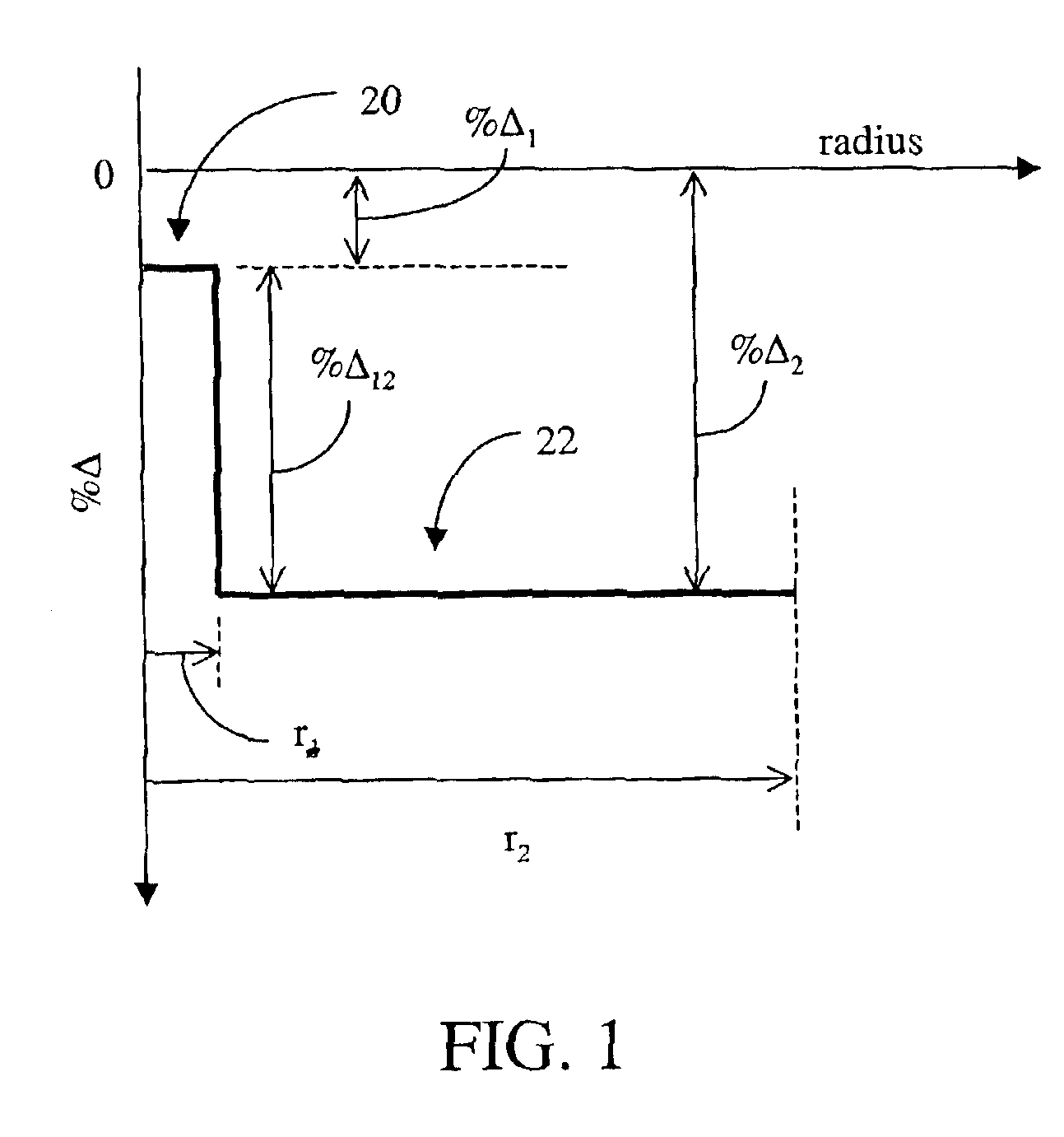
[0078]In a second example, an optical fiber was made using the method described in the example supra. A microprobe analysis of the fiber, shown in FIG. 15, shows the wt. % F (curve 86) and the wt. % Cl (curve 88) as a function of fiber radius. The curves show that the average wt. % F in the core region 20 of the optical fiber was about 0.6 wt. % and the average wt. % Cl in the core region 20 was about 0.2 wt. %. The average wt. % F in the cladding region 22 is about 1.6 wt. %. The optical fiber represented by FIG. 15 would be expected to have a core relative refractive index % Δ1 of about −0.146% and a Tg1 of about 176.9 C. The cladding region would be expected to have a % Δ2 of −0.432% and a Tg2 of about 261.3° C. The expected difference between Tg1 and Tg2 was calculated to be 84.4° C.


PUM

PropertyMeasurementUnit
draw speedaaaaaaaaaa
viscosityaaaaaaaaaa

Abstract

An optical fiber is disclosed in which the core region of the optical fiber is doped with Cl and F in order to reduce the viscosity mismatch between the core region and the adjacent cladding region. In one embodiment of the invention, the optical fiber is a single-mode step index optical fiber having a core region doped with Cl and F in an amount effective to produce a difference in temperature between the glass transition temperature of the core region and the glass transition temperature of the adjacent cladding region of less than about 200° C.

Description

BACKGROUND OF THE INVENTION[0001]1. Field of the Invention[0002]The present invention relates generally to an optical fiber, and particularly to an optical fiber having a reduced viscosity mismatch between the core region and an adjacent cladding segment.[0003]2. Technical Background[0004]Conventional single-mode optical fibers typically have an SiO2 (silica) glass core region doped with a dopant suitable for raising the refractive index of the core region, and surrounded by a cladding glass of pure silica. A typical core region dopant is GeO2. The index difference between the core and the cladding is necessary to create a light guide wherein propagating light is generally confined to the core region. The concentration of GeO2 found in a conventional single-mode doped-core optical fiber may be in excess of 7 weight percent (wt. %). Because the high concentration of dopant is located in the core region of the optical fiber, the optical loss, or attenuation, of the optical fiber is hi...

Claims


Application Information

Patent Timeline
Patent Type & Authority Patents(United States)
IPC IPC(8): C03C13/04C03C13/00C03B37/014G02B6/036G02B6/02
CPCC03B37/01446C03C13/045G02B6/02G02B6/03605G02B6/03627G02B6/03694C03B2201/12C03B2201/20C03B2203/223C03B2203/24C03C13/00G02B6/00
Inventor BOEK, HEATHER D.MURTAGH, MICHAEL T.SEN, SABYASACHI
Owner CORNING INC
Why Eureka
Try Eureka