Compact hybrid integrated optical dynamic channel equalizer

a hybrid, optical dynamic channel technology, applied in the direction of optical elements, multiplex communication, instruments, etc., can solve the problems of significant power and signal to noise ratio (snr) differential between the various channels, affecting the proper functioning of the optical network, and the different gain levels of the different channels in the optical network

Inactive Publication Date: 2005-07-12
NAT RES COUNCIL OF CANADA
View PDF6 Cites 7 Cited by
  • Summary
  • Abstract
  • Description
  • Claims
  • Application Information

AI Technical Summary

Problems solved by technology

However, due to the existence of non-uniform EDFA gain with wavelength, variable channel insertion losses in the components, neighboring channel addition and deletion, unstable laser power, microsecond long gain transients in EDFA cascades, etc., the gain levels of different channels in an optical network are varied.
This hinders the proper functioning of optical networks.
With the channel power variation, the lower gain channels progressively lose power relative to the higher gain channels, causing a significant power and signal to noise ratio (SNR) differential among the various channels, and limiting the transmission distance and usable amplifier bandwidth.
In addition, as channel powers vary in a dynamic network, several system complications may arise which can potentially cause network failure, such as changes in the input signal powers, drift in component wavelength selectivity, changes in link losses and changes in amplifier gain.
Various types of optical dynamic channel equalizer have been proposed or developed in recent years, but most of them are expensive and bulky. FIG. 1 (prior art) shows the general operation of such a dynamic channel equalizer as disclosed by U.S. Pat. No. 6,345,133.
As can be seen from FIG. 1, such a dynamic channel gain equalizer uses one MUX and two DMUXs, which renders the devices expensive and bulky.
Due to the employment of the optical coupler 93, the manufacture of such a device is relatively complicated and expensive.

Method used


Image

  • Compact hybrid integrated optical dynamic channel equalizer
  • Compact hybrid integrated optical dynamic channel equalizer
  • Compact hybrid integrated optical dynamic channel equalizer

Examples


Embodiment Construction

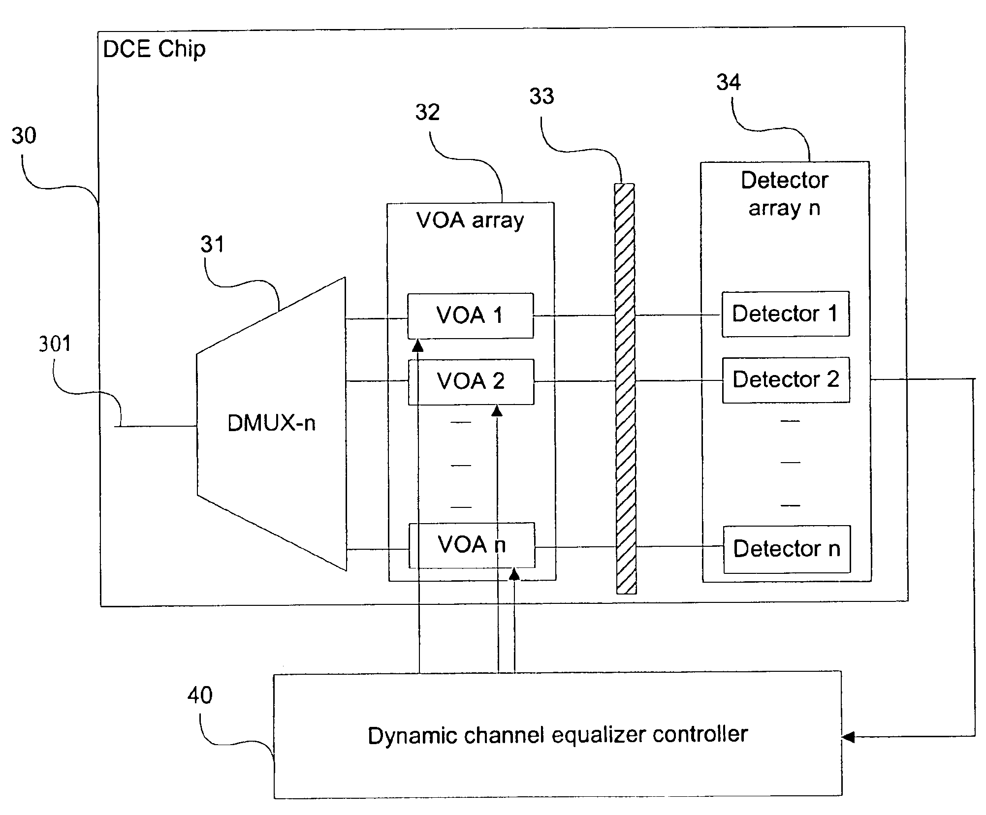
[0021]Generally, the present invention provides a method and system for equalizing channel gain levels in a WDM transmission line. In its simplest embodiment, the equalizer comprises an optical demultiplexer, a variable optical attenuator array, a partially transparent reflector and an equalization controller. The optical demultiplexer receives an optical signal and demultiplexes it into a plurality of optical channel signals. The variable optical attenuator array has a plurality of variable optical attenuators. Each variable optical attenuator receives and attenuates one of the plurality of optical channel signals. The partially transparent reflector is positioned to reflect a portion of each attenuated optical channel signal to an optical multiplexer, and to transmit a portion of the remainder of each attenuated optical channel signal. The equalization controller receives the transmitted portions and controls each variable optical attenuator, by feedback, based on a comparison bet...


PUM


Abstract

An integrated optical dynamic channel equalizer that can be employed to equalize the channel gain level in a WDM transmission line and monitor the optical channel performance. The device consists of a circulator, a dynamic gain equalizer chip and a controller. Due to the simplicity of the dynamic gain equalizer chip, which includes one 1×n multiplexer / demultiplexer, an n-channel variable optical attenuator array (VOA-n), a partially transparent dielectric reflective means and an n-channel detector array, the device is very compact and can be fabricated at low cost. By placing a quarter wave plate between the n-channel variable optical attenuator array and the partially transparent reflective means in the dynamic channel equalizer chip, the device can be rendered polarization insensitive.

Description

FIELD OF THE INVENTION[0001]The present invention relates generally to optical dynamic channel equalizers. More particularly, the present invention relates to an optical dynamic channel equalizer for application in optical communication networks, particularly, an optical channel equalizer for a WDM network where multiple channels of optical signals are transmitted through an optical transmission line.BACKGROUND OF THE INVENTION[0002]Increasing demand for transmission capacity, high-speed, and / or long-distance data transmissions among multiple users has pushed the development and deployment of fiber-optic communication systems. Technologies making these feasible include wavelength division multiplexing (WDM), and erbium doped fiber amplification (EDFA). In a WDM system, many different wavelength channels are transmitted simultaneously along the optical fibers or data transmission lines. This dramatically increases the capacity of the transmission system and permits wavelength depende...

Claims


Application Information

Patent Timeline
Patent Type & Authority Patents(United States)
IPC IPC(8): G02B6/00G02B6/26H04B10/18H04J14/02
CPCH04J14/0221H04J14/02
Inventor XIAO, GAOZHIZHANG, ZHIYILU, ZHENGUOLIU, JIARENGROVER, CHANDER P.
Owner NAT RES COUNCIL OF CANADA
Why Eureka
Try Eureka