
Coated implantable medical device

Inactive Publication Date: 2005-07-19
COOK MEDICAL TECH LLC
View PDF25 Cites 365 Cited by
  • Summary
  • Abstract
  • Description
  • Claims
  • Application Information

AI Technical Summary

Benefits of technology

[0016]As described in more detail below, the base material of the structure and the bioactive material posited on that base material can comprise any of a wide range of suitable materials. The selection of a specific combination of base material, bioactive material and surface roughness or texture depends upon the intended use of the medical device. Although texture may have a meaning of a repeatable pattern, this is clearly not the intent. The surface of the stent is that of any topography, whether repeatable or not, that helps improve adhesion of the bioactive material on the base material or modification thereof. Hereinafter, a textured surface will include a roughened, uneven, or unsmooth surface. The suitability of a chosen combination can readily be determined by an adhesion test which simulates the actual delivery of bioactive material during introduction and deployment of the device in a patient. Such a test is straightforward and is believed not to entail an undue amount of experimentation, particularly in comparison to the amount and technical level of testing required before a product of this type can be marketed in the United States.
[0017]The medical device of the present invention and its method of manufacture have several advantages over prior stents and other medical devices and methods for manufacturing them. The time and cost of manufacture of the medical device are minimized by the absence of any steps to incorporate the bioactive material in a containment layer, or to apply a containment or time-release layer over the bioactive material. The particularly preferred use of sodium bicarbonate as the abrasive to treat, roughen, or texture the surface of the base material of the structure enjoys several indirect cost savings resulting from the low toxicity of the sodium bicarbonate to production workers, the ease of product and waste cleanup, and the biocompatibility of any residual sodium bicarbonate. Worker safety and ease of product and waste cleanup are, of course, important advantages in their own right.
[0030]Again, as indicated above, the medical device of the present invention and its method of manufacture have several advantages over prior stents and other medical devices and methods for manufacturing them. The time and cost of manufacture of the medical device of the present invention are minimized by the absence of any steps to incorporate the bioactive material in a containment layer, or to apply a containment or time-release layer over the bioactive material. The particularly preferred use of sodium bicarbonate as the abrasive to roughen or texture the surface of the base material of the structure enjoys cost savings resulting from the low toxicity of the sodium bicarbonate to production workers, the ease of product and waste cleanup, and the biocompatibility of any residual sodium bicarbonate. It should go without saying that the good worker safety and ease of product and waste cleanup enjoyed by the method of the present invention are highly desirable advantages, without regard to any costs saved.

Problems solved by technology

Unexpectedly, this straightforward expedient yields a coated implantable medical device which is sufficiently durable to withstand the desired implantation without suffering an unacceptable amount of loss (if any) of bioactive material from the device.

Method used


Image

  • Coated implantable medical device
  • Coated implantable medical device

Examples


Embodiment Construction

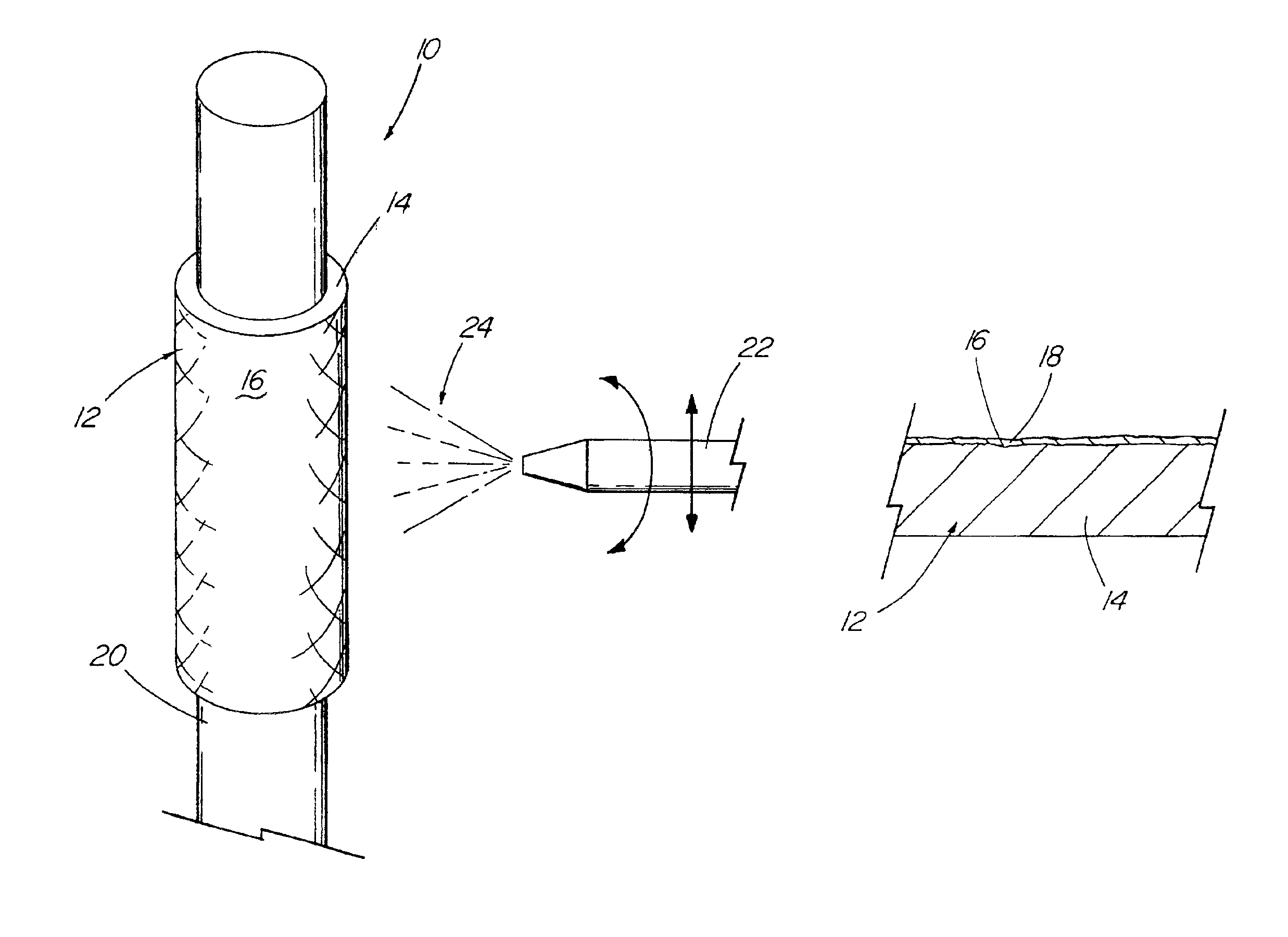
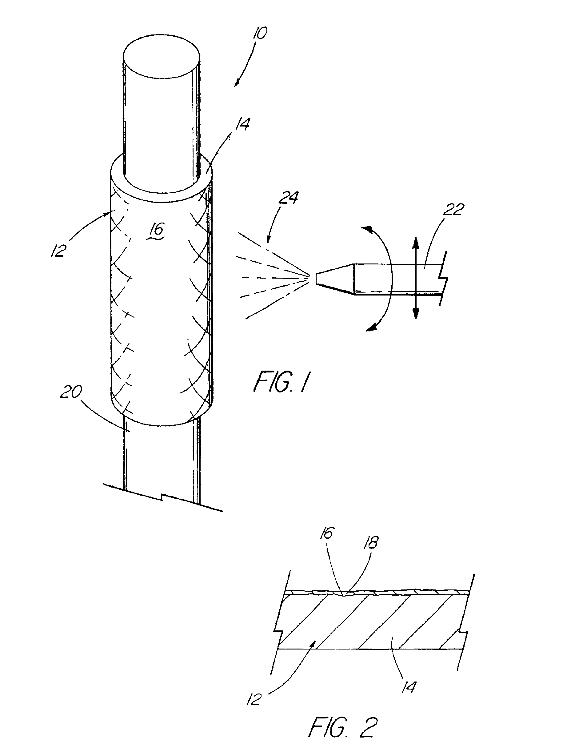
[0034]With reference now to the Figures, an implantable medical device 10 in accordance with the present invention is there shown. The medical device 10 of the present invention first comprises a structure 12 adapted for temporary or permanent introduction into a human or veterinary patient. “Adapted” means that the structure 12 is particularly configured, shaped and sized for such introduction. By way of example, the structure 12 is most preferably configured as a vascular stent adapted for insertion into the vascular system of the patient.

[0035]The structure 12 can of course be particularly configured for use in other systems and sites such as the esophagus, trachea, colon, biliary ducts, urethra and ureters, among others. Indeed, the structure 12 can alternatively be configured as any conventional vascular or other comparable medical device, and can include any of a variety of conventional stent or other adjuncts, such as helically wound strands, perforated cylinders or the like....


PUM

PropertyMeasurementUnit
Lengthaaaaaaaaaa
Nanoscale particle sizeaaaaaaaaaa
Dynamic viscosityaaaaaaaaaa

Abstract

A medical device (10) includes a structure (12) adapted for introduction into a patient, the structure (12) being formed of a preferably non-porous base material (14) having a roughened or textured surface (16). The structure (12) is conveniently configured as a vascular stent with a base material (14) of stainless steel, nitinol or another suitable material. The medical device (10) also includes a layer (18) of a bioactive material posited directly upon the roughened or textured surface (16) of the base material (14) of the structure (12). The surface (16) of the base material (14) is roughened or textured by etching or by abrasion with sodium bicarbonate or another suitable grit. A preferred roughened or textured surface (16) is thought to have a mean surface roughness of about 10 μin. (about 250 nm) and a surface roughness range between about 1 μin. and about 100 μin. (about 25 nm and about 2.5 μm). The particularly preferred use of sodium bicarbonate as the abrasive to provide roughness or texture to the surface (16) of the base material (14) of the structure (12) is additionally advantageous in the low toxicity of the sodium bicarbonate to production workers, the ease of product and waste cleanup, and the biocompatibility of any residual sodium bicarbonate.

Description

RELATED APPLICATION INFORMATION[0001]This application claims priority from U.S. Provisional Application Ser. No. 60 / 244,446 filed Oct. 31, 2000.TECHNICAL FIELD[0002]This invention relates generally to human and veterinary medical devices and, more particularly, to devices incorporating drugs, bioactive agents, therapeutic agents or diagnostic agents.BACKGROUND OF THE INVENTION[0003]It has become common to treat a variety of medical conditions by temporarily or permanently introducing an implantable medical device partly or completely into the esophagus, trachea, colon, biliary tract, urinary tract, vascular system or other location within a human or veterinary patient. Many treatments of the vascular or other systems entail the introduction of a device such as a stent, a catheter, a balloon, a wire guide, a cannula or the like. For this purpose, a stent may most simply be considered as a cylinder of relatively short length which opens a body passage or lumen or which maintains a bod...

Claims


Application Information

Patent Timeline
IPC IPC(8): A61L27/00A61L27/54A61L31/14A61L31/16A61L29/00A61F2/00A61F2/86A61K31/337A61K31/4545A61P9/10A61P35/00
CPCA61L27/54A61L31/16A61F2/86A61F2250/0067A61L2300/252A61L2300/414A61L2300/606A61P35/00A61P9/10A61L27/28
Inventor BATES, BRIAN L.RAGHEB, ANTHONY O.STEWART, IV, JOSEPH M.BOURDEAU, WILLIAM J.CHOULES, BRIAN D.PURDY, JAMES D.FEARNOT, NEAL E.
Owner COOK MEDICAL TECH LLC
Learn More