Discharge lamp having an auxiliary light source to produce light with a short wavelength

a technology of auxiliary light source and discharge lamp, which is applied in the direction of transit tube circuit elements, structural circuit elements, cathode-ray/electron beam tube circuit elements, etc., can solve the problems of high cost, increased and complicated arrangement, so as to increase the probability of producing fault-free products and the reliability of finished parts

Inactive Publication Date: 2005-07-19
USHIO DENKI KK
View PDF23 Cites 23 Cited by
  • Summary
  • Abstract
  • Description
  • Claims
  • Application Information

AI Technical Summary

Benefits of technology

[0029]that the probability of producing fault-free produc

Problems solved by technology

This will remove the disadvantages:that the arrangement is complicated and that costs are high; andthat

Method used


Image

  • Discharge lamp having an auxiliary light source to produce light with a short wavelength
  • Discharge lamp having an auxiliary light source to produce light with a short wavelength
  • Discharge lamp having an auxiliary light source to produce light with a short wavelength

Examples


Embodiment Construction

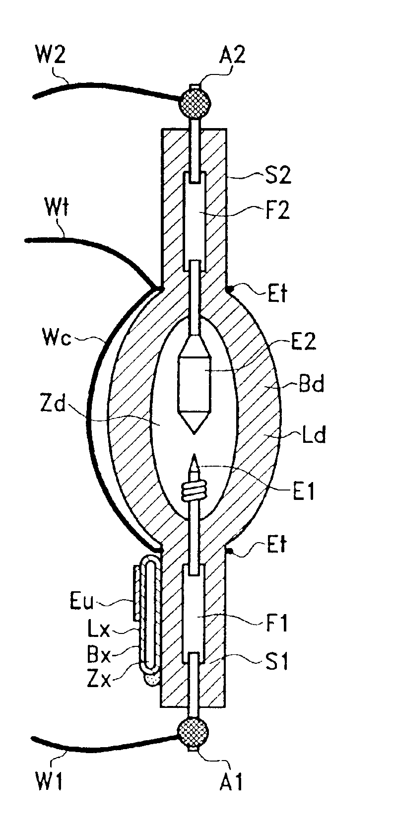
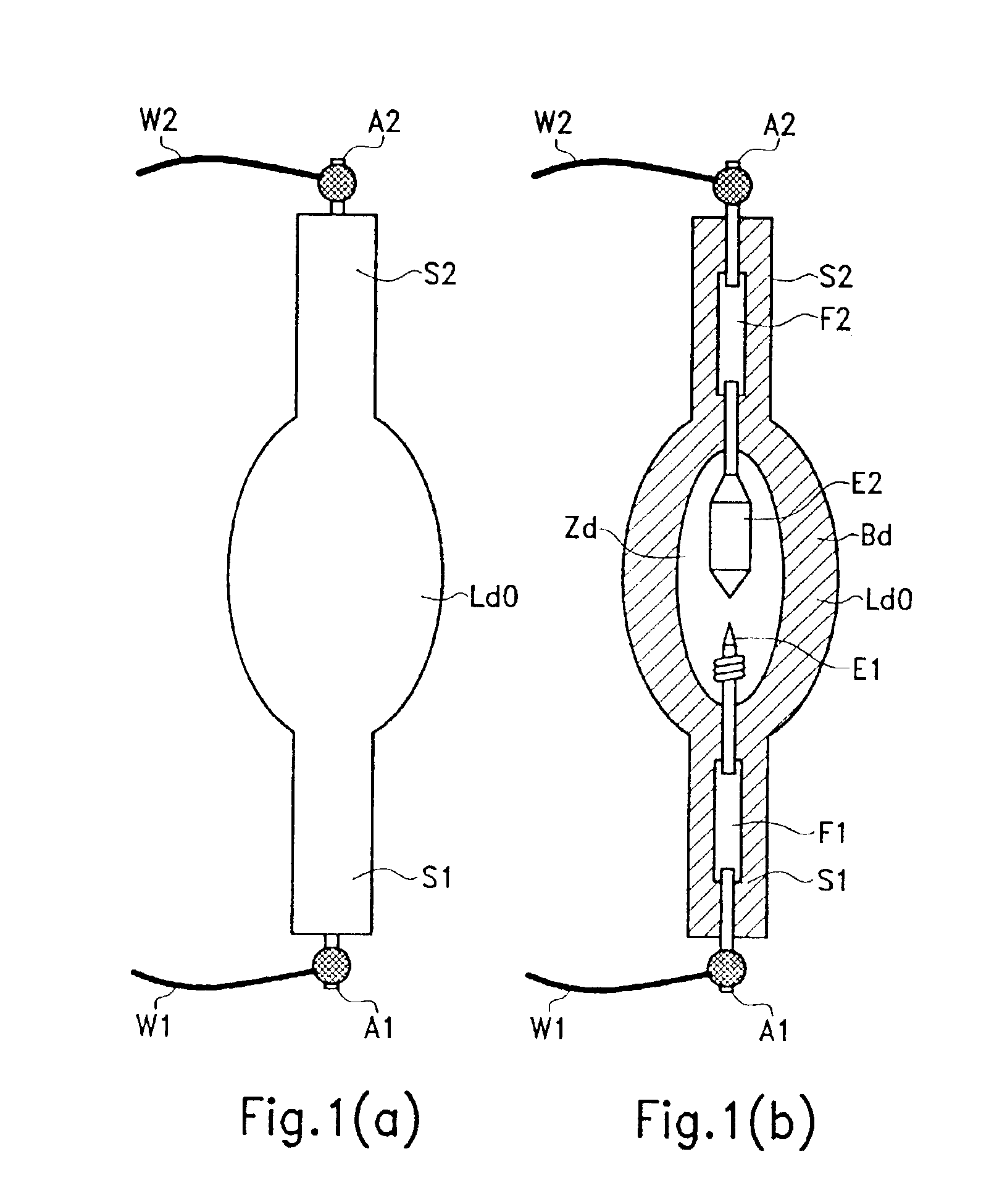
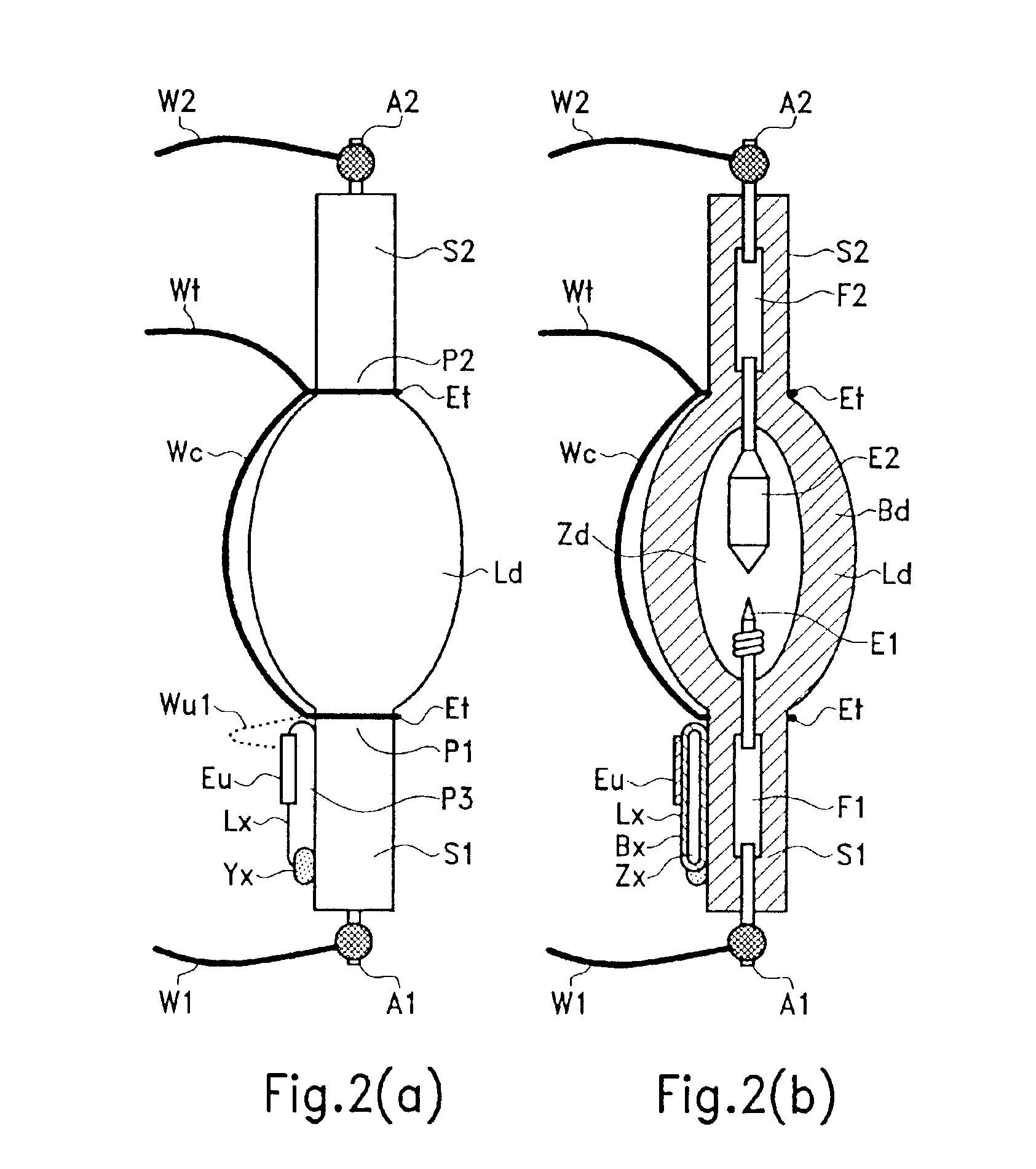
[0049]FIGS. 1(a) &1(b) show the embodiment of a lamp for direct current operation. For the pair of electrodes (E1, E2) for the main discharge which are located opposite, one electrode (E1) is the cathode and the other electrode (E2) is the anode. The discharge space (Zd) for the main discharge, which is surrounded by the main discharge vessel (Bd) which comprises silica glass or the like, is filled with a discharge medium for the main discharge.

[0050]In the electrode sealing parts (S1, S2) which are made integral with the main discharge vessel (Bd) and which also comprise silica glass or the like, there are metal foils (F1, F2) and outer leads (A1, A2) which arc used for electrical connection to the electrodes (E1, E2) from outside the main discharge space (Zd) and for hermetic sealing. The electrode (E1), the metal foil (F1) and the outer lead (A1) are electrically connected to one another by spot welding or the like. Similarly, the electrode (E2), the metal foil (F2) and the outer...


PUM


Abstract

The discharge lamp of the invention includes a main discharge vessel which is filled with a discharge medium for the main discharge via a pair of opposed main discharge electrodes, and has a first electrode sealing part and a second electrode sealing part for connecting the pair of main discharge electrodes. The advantage of the invention is in a starting electrode arranged such that it does not come into contact with the main discharge space, and an auxiliary light source which includes an auxiliary discharge vessel located adjacent on the side of one of the electrode sealing parts and which is not made integral with the electrode sealing parts. The auxiliary light source is filled with a discharge medium, and has a first outer electrode on the outside of the auxiliary discharge vessel.

Description

BACKGROUND OF THE INVENTION[0001]1. Field of the Invention[0002]The invention relates to a discharge lamp with high radiance (HID lamp), such as a high pressure mercury discharge lamp, a metal halide lamp or the like, which is used for example as a light source for a projector.[0003]2. Description of Related Art[0004]In a light source device for an optical device such as a liquid crystal projector, a DLP projector or the like, a discharge lamp with high radiance, such as a high pressure mercury discharge lamp, a metal halide lamp, or the like is used. In these discharge lamps it is generally necessary when starting to apply a high voltage between the main discharge electrodes or between the electrode for the main discharge and the inside of the discharge vessel, to produce an insulation breakdown in the discharge medium within the discharge vessel, and to induce a glow discharge or an arc discharge, the electrons of the plasma which has been produced thereby acting as the triggering...

Claims


Application Information

Patent Timeline
IPC IPC(8): H01J61/54
CPCH01J61/547
Inventor OKAMOTO, MASASHIYAMASHITA, TAKASHI
Owner USHIO DENKI KK
Why Eureka
Try Eureka