
Method of and apparatus for controlling writing power in an optical drive

a technology of optical drives and writing power, applied in the direction of optical beam sources, recording signal processing, instruments, etc., can solve the problems of difficult to achieve satisfactory writing characteristics, and the inability to control the writing power of the ld to be in an optimal sta

Inactive Publication Date: 2005-07-19
SAMSUNG ELECTRONICS CO LTD
View PDF2 Cites 9 Cited by
  • Summary
  • Abstract
  • Description
  • Claims
  • Application Information

AI Technical Summary

Benefits of technology

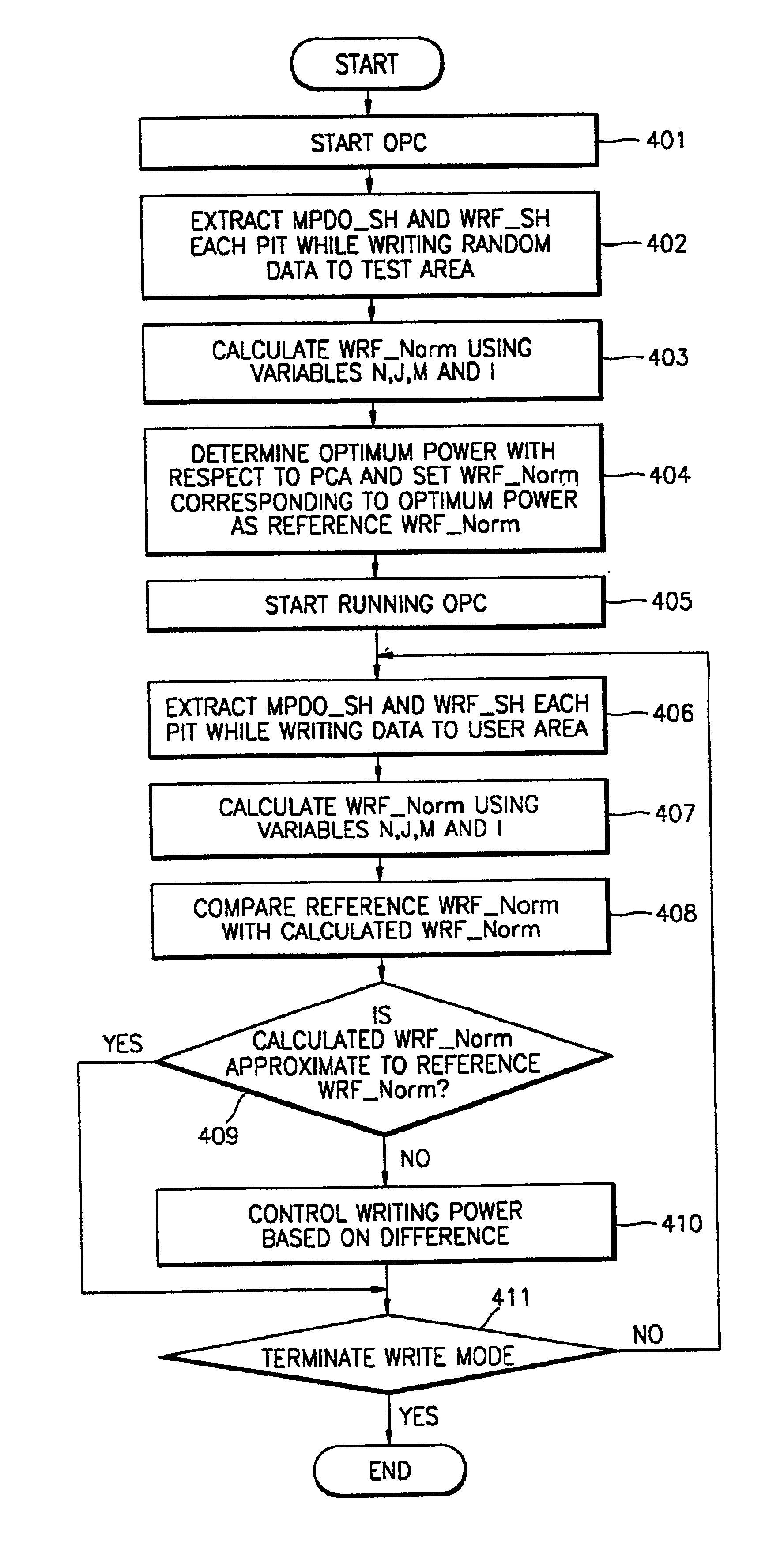
[0010]To solve the above problem, it is an object of the present invention to provide a method of and an apparatus for controlling writing power to an optical medium to perform running optimum power control (OPC). According to the present invention a deficiency in dynamic ranges of monitored writing power and a write radio frequency (RF) signal, which are difficult to compensate in hardware, is compensated for in firmware (or software) and a normalized write RF signal having a constant linear characteristic is obtained to control the writing power of a laser diode while an optical drive is in a write mode, thereby attaining an optimum writing characteristic where the writing environment of the optical drive changes.

Problems solved by technology

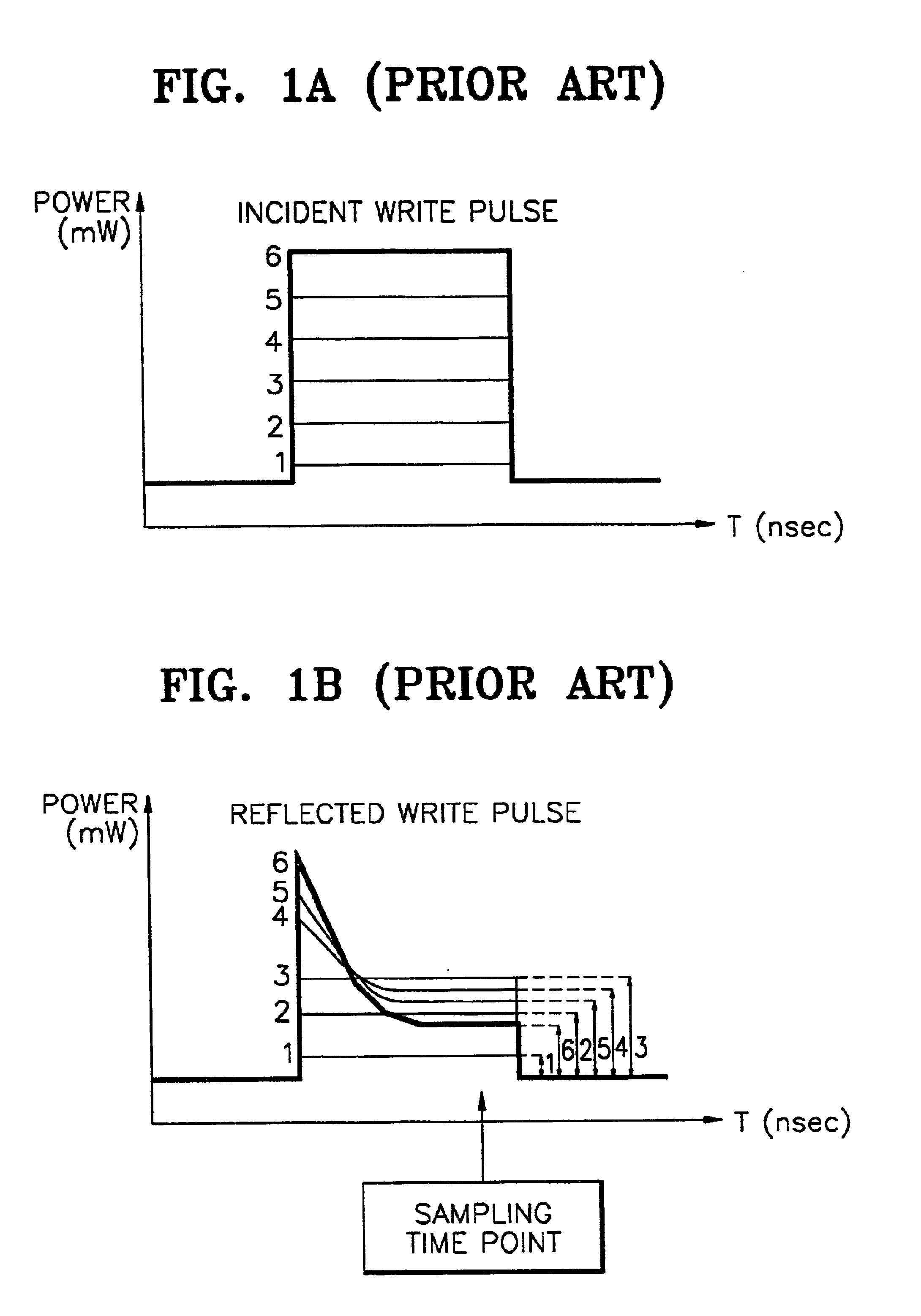
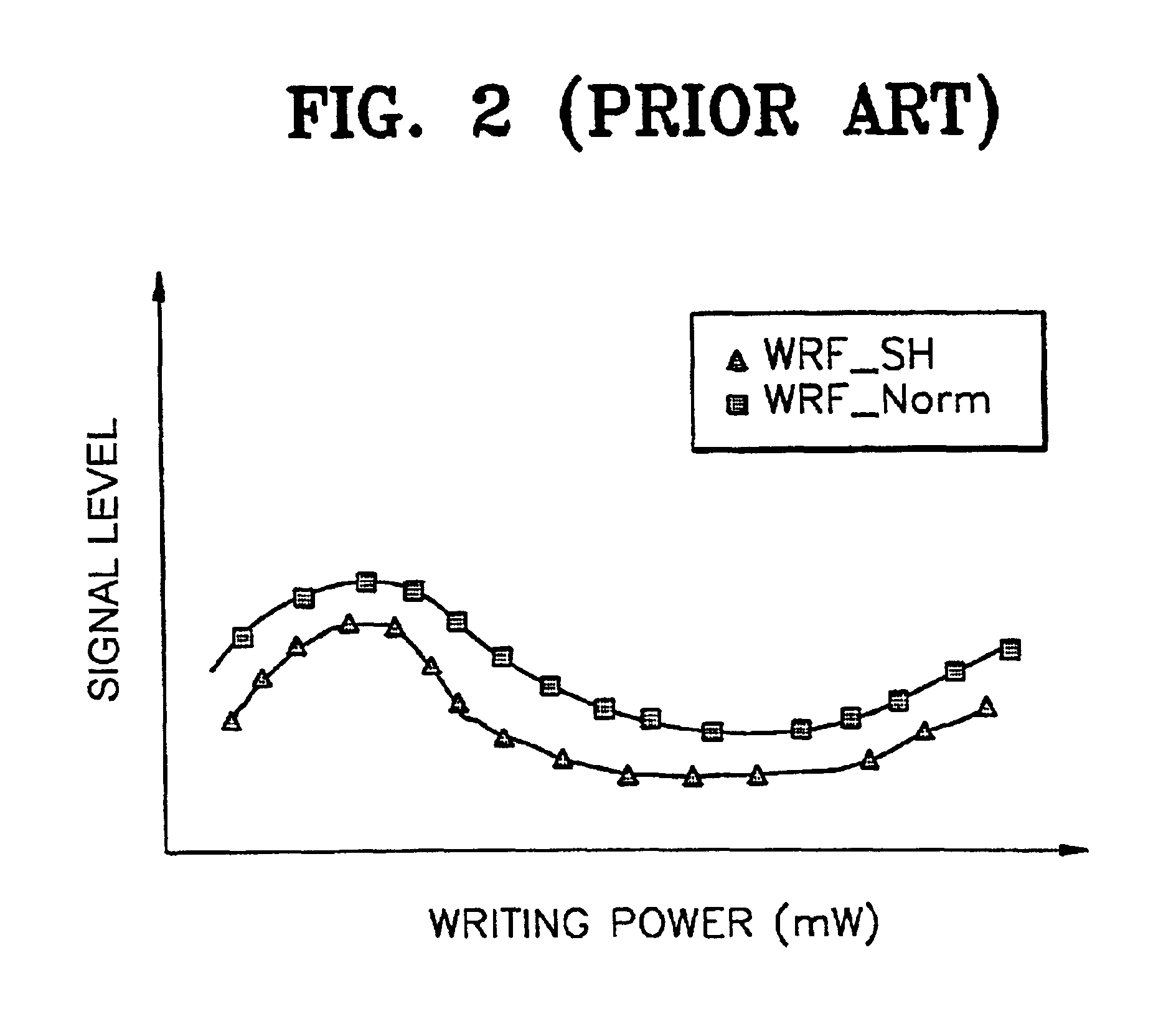
However, since values of the WRF and the MPDO are not suitable for obtaining a sufficient dynamic range in hardware, WRF_Norm obtained using WRF_SH and MPDO_SH has a nonlinear characteristic, as shown in FIG.
Accordingly, when skew exists due to an optical medium or a deck mechanism, where the wavelength of the LD changes due to high temperature, or where deviation occurs in an optical medium, control of the writing power of the LD to be in an optimum state becomes impossible.
As such, a difference in a land jitter between the inner track and the outer track increases so that it is difficult to attain a satisfactory writing characteristic.

Method used


Image

  • Method of and apparatus for controlling writing power in an optical drive
  • Method of and apparatus for controlling writing power in an optical drive
  • Method of and apparatus for controlling writing power in an optical drive

Examples


Embodiment Construction

[0024]Reference will now be made in detail to the present embodiments of the present invention, examples of which are illustrated in the accompanying drawings, wherein like reference numerals refer to like elements throughout.

[0025]Referring to FIG. 3, an optical drive for controlling writing power according to the present invention comprises a controller 301, an automatic power controller (APC) 302, a laser diode (LD) drive 303, an LD 304, a beam splitter 305, an objective lens 306, a photo diode 308, a monitoring photo diode 309, sampling and hold units 310 and 311, a voltage gain amplifier 312, and a static random access memory (SRAM) 313. The optical drive records / reads information to / from an optical medium 307 such as, for example, a CD-R or a CD-RW.

[0026]While data is written to the optical medium 307 in a write mode in response to a user's command, the controller 301 detects a normalized write radio frequency (RF) signal (referred to as WRF_Norm) having a linear characteristi...


PUM


Abstract

An apparatus for and a method of performing running optimum power control (OPC) of a laser diode writing power in an optical drive. The apparatus and method obtain an optimum writing characteristic where the writing environment of the optical drive changes. A first normalized write signal having a first linear characteristic with respect to writing power is detected using predetermined condition values to set a first normalized write signal as a reference signal. A second normalized write signal having a second linear characteristic with respect to writing power is detected using the predetermined condition values, while writing data to a user area on the optical medium. The writing power of the laser diode is controlled based on determining whether the second normalized write signal is approximate to the first normalized write signal.

Description

CROSS REFERENCE TO RELATED APPLICATIONS[0001]This application claims the benefit of Korean Application No. 2001-3417 filed Jan. 20, 2001 in the Korean Patent Office, the disclosure of which is incorporated herein by reference.BACKGROUND OF THE INVENTION[0002]1. Field of the Invention[0003]The present invention relates to a method of and an apparatus for controlling writing power in an optical drive, and more particularly, to a method of and an apparatus for controlling power for driving a laser diode (LD) in a write mode, thereby obtaining an optimum writing characteristic where a writing environment changes.[0004]2. Description of the Related Art[0005]Conventional optical drives control a level of laser power (or writing power) necessary for writing data to an optical medium such as a Compact Disc Recordable (CD-R) or a Compact Disc ReWritable (CD-RW), to which data may be additionally written or rewritten, using a power calibration area (PCA) on the optical medium in a write mode....

Claims


Application Information

Patent Timeline
IPC IPC(8): G11B7/125G11B7/0045G11B7/00G11B7/1263G11B7/1267
CPCG11B7/00458G11B7/1263G11B7/1267G11B7/0045
Inventor KIM, JOO-YOUP
Owner SAMSUNG ELECTRONICS CO LTD
Learn More