Process and apparatus for the pyrolysis of hydrocarbon gas
a hydrocarbon gas and hydrocarbon gas technology, applied in the direction of gas-gas reaction process, thermal non-catalytic cracking, combustible gas production, etc., can solve the problems of increasing the cost of equipment, the coking of the interior of the tube, and the complexity of equipment, so as to reduce the cost of equipmen
- Summary
- Abstract
- Description
- Claims
- Application Information
AI Technical Summary
Benefits of technology
Problems solved by technology
Method used
Image

Examples
first embodiment
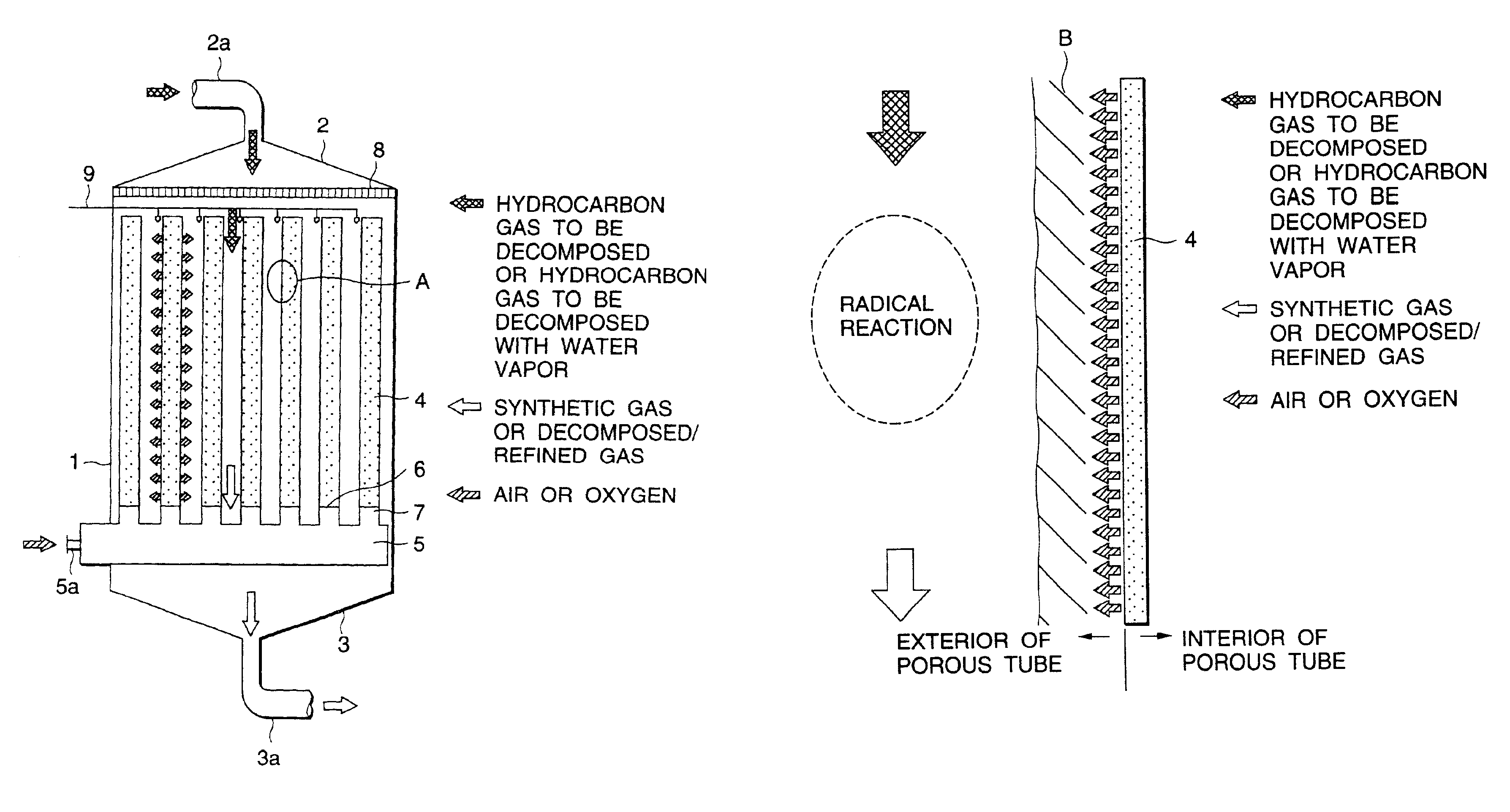
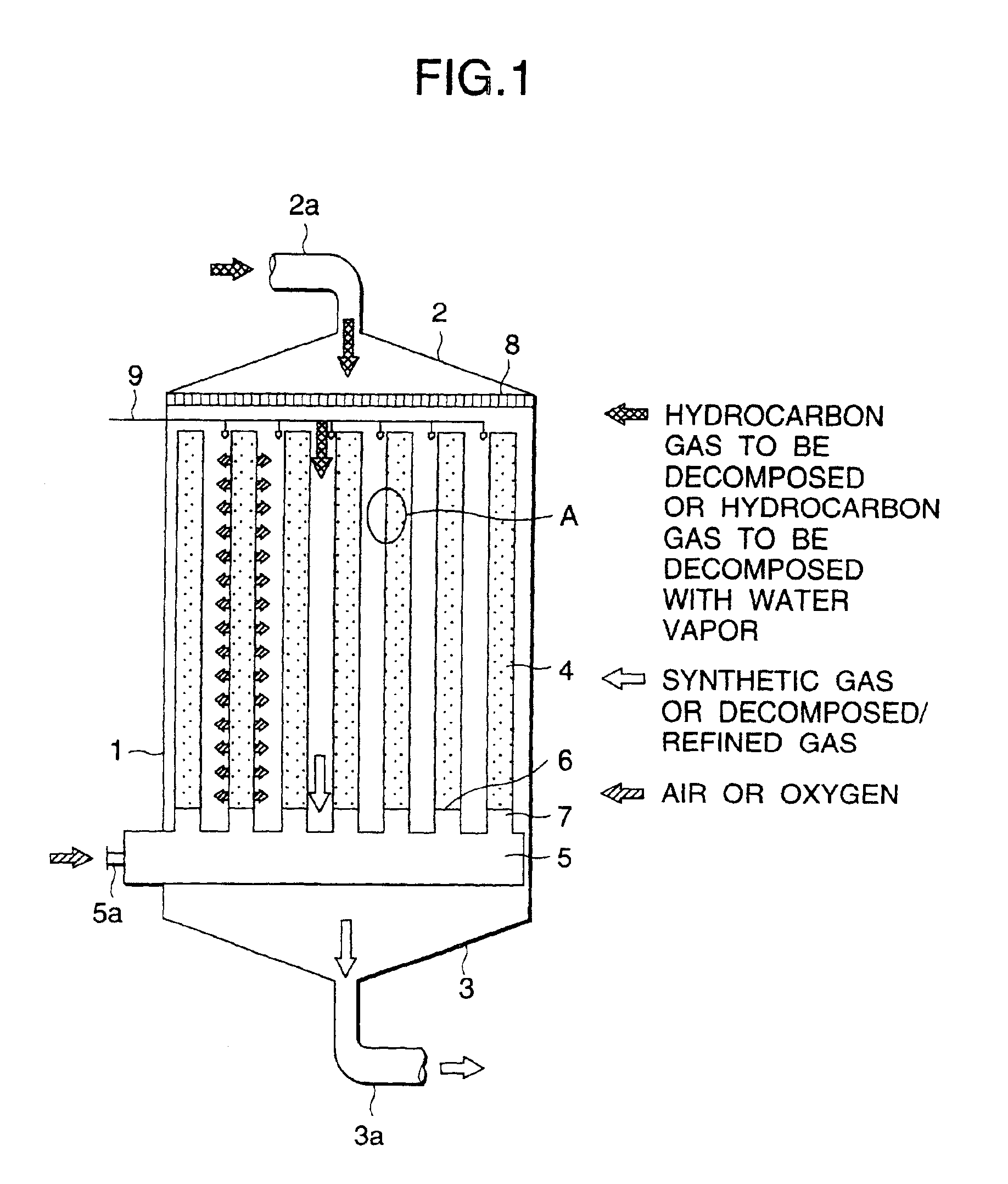
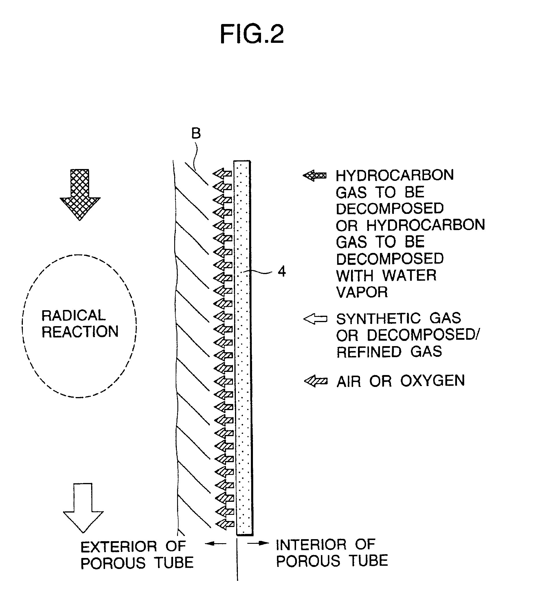
[0023]FIG. 1 is a diagram illustrating the concept of an apparatus for the pyrolysis of a hydrocarbon gas according to the first example of the invention. In this diagram, the reference numeral 1 indicates a decomposition reaction column comprising a diffuser 2 provided at the upper portion thereof and a reducer 3 provided at the lower portion thereof. Provided extending vertically in the decomposition reaction column 1 are a group of porous tubes. The reaction column may be cylindrical or prismatic.
[0024]The various porous tubes constituting the foregoing group of porous tubes are each made of a porous metal or a metal film material having a pore size of the order of MF (microfiltration) or UF (ultrafiltration). As the porous metal or metal film material there may be used SUS, tool steel, inconnel, titanium alloy, aluminum alloy or the like.
[0025]The various porous tubes constituting the foregoing group of porous tubes are each made of a porous metal or a metal film material having...
second embodiment
[0032]FIG. 3 is a diagram illustrating the concept of an apparatus for the pyrolysis of a hydrocarbon gas according to the second example of the invention. Since the present example differs from the first example only in that non-porous tubes 10 are provided concentrically of the porous tubes 4 surrounding the periphery of the porous tubes 4, respectively, with a gap interposed therebetween, the description of other structures will be omitted. In some detail, as shown in FIG. 4, air is allowed to flow through the inner tube of a double tube consisting of the porous tube 4 as an inner tube and the non-porous tube 10 as an outer tube while a hydrocarbon gas to be decomposed, optionally mixed with water vapor, is allowed the flow space (double tube portion) defined by the inner tube and the outer tube, whereby the hydrocarbon gas to be decomposed undergoes radical reaction as in the first example to produce a gaseous olefinic organic compound having a shorter chain chemical composition...
third embodiment
[0036]FIG. 6 is a diagram illustrating the concept of an apparatus for the pyrolysis of a hydrocarbon gas according to the third example of the invention. In this embodiment, the upper portion of reaction column is the same as the structure described in the first embodiment, and the lower portion corresponds to the gas rapidly cooling column 100 for the pyrolyzed gas produced in the upper portion. Coolant spraying tubes 14 are arranged along an inner peripheral portion of the gas rapidly cooling column 100.
[0037]The operation of this device will be described hereinafter.
[0038]The pyrolyzed gas produced in the reaction column as shown in FIG. 1 is transferred directly from the reaction column 1 to the gas rapidly cooling column 100. A coolant sprays from a slit or a spraying hole provided on the coolant spray tubes toward the gas flow path in such a manner that the coolant sprays slantly with respect to the center of a gas cooling portion to meet the spiral air flow in the gas rapidl...
PUM
| Property | Measurement | Unit |
|---|---|---|
| temperature | aaaaa | aaaaa |
| chemical composition | aaaaa | aaaaa |
| time | aaaaa | aaaaa |
Abstract
Description
Claims
Application Information
 - R&D
- Intellectual Property
- Life Sciences
- Materials
- Tech Scout
- Unparalleled Data Quality
- Higher Quality Content
- 60% Fewer Hallucinations
Browse by: Latest US Patents, China's latest patents, Technical Efficacy Thesaurus, Application Domain, Technology Topic, Popular Technical Reports.
© 2025 PatSnap. All rights reserved.Legal|Privacy policy|Modern Slavery Act Transparency Statement|Sitemap|About US| Contact US: help@patsnap.com