High frequency network multiplexed communications over various lines using multiple modulated carrier frequencies

a technology of multiplexing communications and carrier frequencies, applied in the field of power system communication improvement, can solve problems such as envelope delay distortion, signal distortion, and particularly severe distortion

Inactive Publication Date: 2005-07-26
SATIUS
View PDF15 Cites 302 Cited by
  • Summary
  • Abstract
  • Description
  • Claims
  • Application Information

AI Technical Summary

Benefits of technology

[0012]a coupler connected between the electrical line and the transmitter, the coupler matching the output impedance of the transmitter means to the characteristic impedance of the electrical line and communicating the modulated carrier signals to the electrical line without substantial phase distortion.
[0016]a first coupler connected between the electric line and the transmitter, said coupler matching the output impedance of the transmitter to the characteristic impedance of the electric line and communicating the modulated carrier signal to the electric line without substantial phase distortion;
[0019]a second coupler connected between the electric line and the receiver for matching the input impedance of the receiver to the characteristic impedance of the electric line and communicating the modulated carrier signal to the receiver without significant phase distortion.
[0024]a first coupler connected between the electric lines and the first transmitter and the first receiver, said first coupler matching the output impedance of the first transmitter and the input impedance of the first receiver to the characteristic impedance of the electric lines and communicating the first and second modulated carrier signals without substantial phase distortion;
[0028]a second coupler connected between the electric lines and the second transmitter and the second receiver, said second coupler matching the output impedance of the second transmitter and the input impedance of the second receiver to the characteristic impedance of the electric lines and communicating the first and second modulated carrier signals without substantial phase distortion.

Problems solved by technology

A significant problem associated with prior art power-line carriers is their requirement for one or more line traps, one or more capacitors, one or more coupling transformers or carrier frequency hybrid circuits and frequency connection cables.
All traditional couplers incorporate a ferrite or iron core transformer which causes signal distortion due to the non-linear phase characteristic of the transfer function between the transmit coupler and the receive coupler.
For distribution power-line carriers, the distortion is particularly severe because the signal must propagate through at least three such non-linear devices, the distribution transformer and two power-line couplers, that use ferrite core transformers.
The distortion caused by these non-linear devices leads to envelope delay distortion, which limits communication speeds.
This results in a mistuning of the desired carrier frequency.
Also, the impedance of the primary winding at the desired carrier frequency is no longer matching the power line characteristic impedance.
This results in a significant coupling loss of up to 20 dB at the carrier frequency.
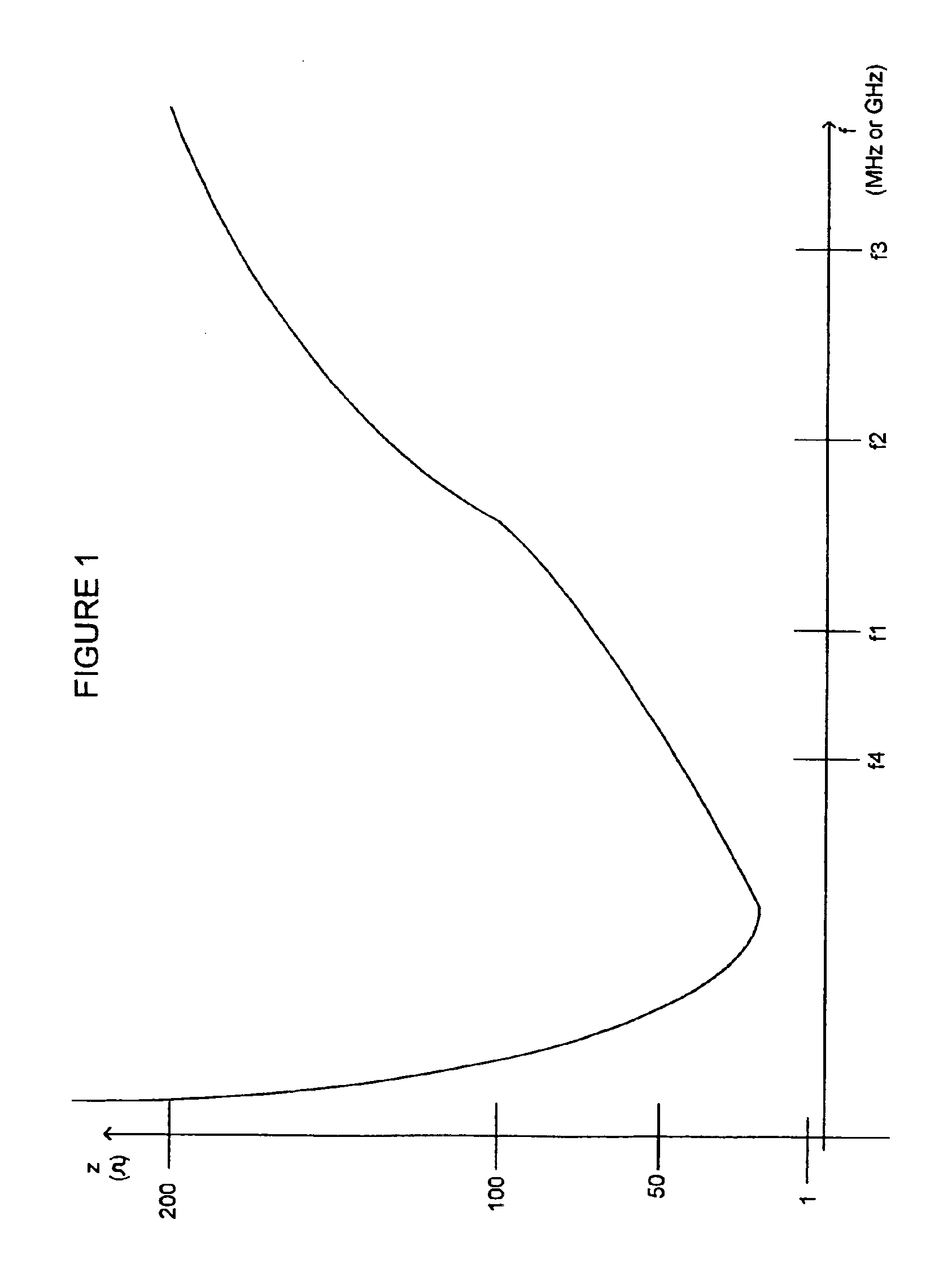
The designs described in U.S. Pat. No. 6,407,987 solved many of the problems of previous designs, which used ferrite or iron couplers that resonated with the power line characteristic impedance, resulting in notches, suck outs and non-linear media for communications over various lines such as power lines.

Method used


Image

  • High frequency network multiplexed communications over various lines using multiple modulated carrier frequencies
  • High frequency network multiplexed communications over various lines using multiple modulated carrier frequencies
  • High frequency network multiplexed communications over various lines using multiple modulated carrier frequencies

Examples


Embodiment Construction

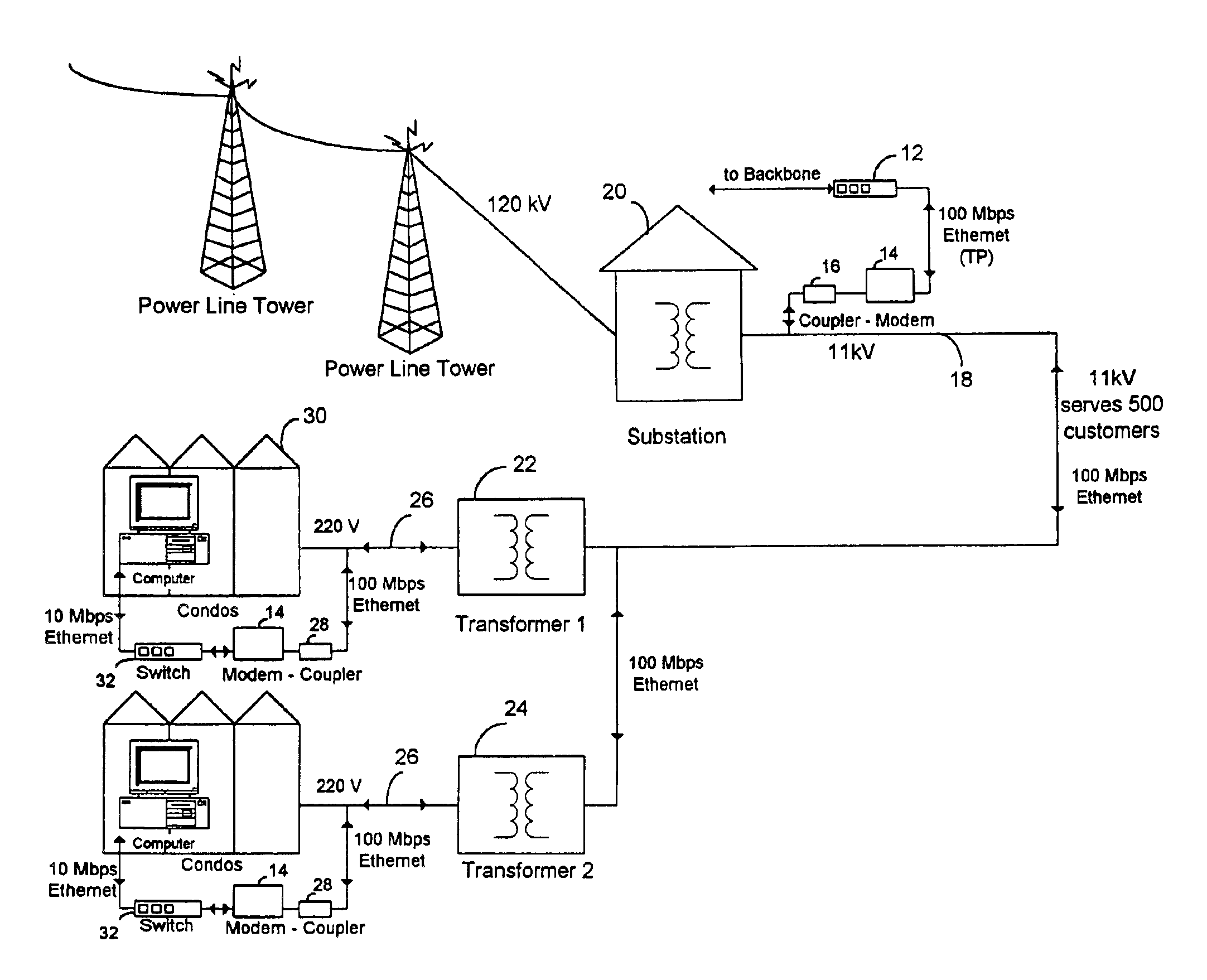
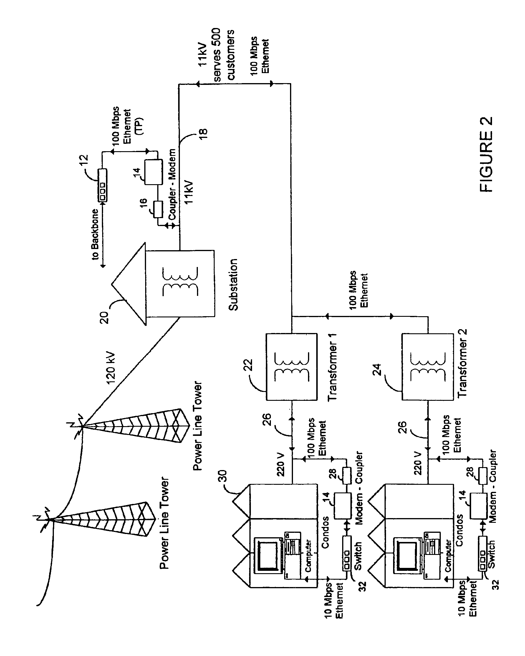
[0044]The present invention presents improvements to the phase shift linear coupler in U.S. Pat. No. 6,407,987. It has been discovered that using higher frequencies (1-500 GHz) with an air-core or dielectric core coupler produces better results because it has wider bandwidth and can transmit for further distances. The higher frequency signals will create a magnetic field around any type of wire and will travel along the surface of a power line like a magnetic wave and jump transformers. Therefore the transmission of such high frequency signals can be achieved for long distances with wide bandwidth.

[0045]In a controlled environment like a coax cable, a high frequency signal of 1 GHz or more will travel only a short distance before it will disappear. This is because a coax cable has a high fixed serial inductance L and a parallel capacitance C which result in a strong low pass filter that can eliminate signals of every frequency at a certain distance. Also, a coax cable can only creat...


PUM


Abstract

An apparatus is provided for high frequency multiplexed electrical line communication for cable TV, telephone, internet, security and other control applications over the mid and low voltage power lines and directly through the transformers. The apparatus includes a transmitter, a receiver, a modem, a multiplexer and multiple couplers at each of two or more locations along an electrical line. The couplers have capacitive circuits serially connected with an air-core or dielectric-core transformer. The capacitive circuits resonate with the transformer at a preselected frequency. The coupler eliminates noise and is matched to the characteristic impedance of the line at the preselected frequency, which linearizes communication on the line and allows high speed data and voice communication over long distances. Multiple modulators and demodulators are used to produce multiple modulated carrier frequencies.

Description

CROSS-REFERENCE TO RELATED APPLICATIONS[0001]This application is a continuation of PCT International Patent Application No. PCT / US03 / 03045 designating the United States, filed on Jan. 31, 2003 which is a continuation-in-part of U.S. application Ser. No. 10 / 061,798, filed Feb. 1, 2002, now U.S. Pat. No. 6,686,832, which is a continuation-in-part of U.S. application Ser. No. 09 / 576,981, filed May 23, 2000, now U.S. Pat. No. 6,396,392. All of the above patent applications and U.S. patents are incorporated herein by reference.BACKGROUND OF THE INVENTION[0002]The present invention relates generally to improved power system communications, and more particularly to apparatus capable of simultaneously transmitting and receiving multiple multiplexed digital data signals both at high rates and over long distances through power lines and power line transformers, including AC, DC, coaxial cables, and twisted pair lines.[0003]“Power-line Carriers” are well known in the field of power system comm...

Claims


Application Information

Patent Timeline
Patent Type & Authority Patents(United States)
IPC IPC(8): H04B3/54H04B3/56
CPCH04B3/542H04B3/56H04L25/0266H04B2203/5408H04B2203/5425H04B2203/5445H04B2203/545H04B2203/5483H04B2203/5491
Inventor ABRAHAM, CHARLES
Owner SATIUS
Why Eureka
Try Eureka