Multi-wavelength cross-connect optical switch

a cross-connect optical switch and fiber optic communication technology, applied in the direction of optical radiation measurement, instruments, spectrophotometry/monochromators, etc., can solve the problems of poor cross-talk rejection, inability to easily scale to a larger number of ports, and certain fundamental limitations. achieve high cross-talk rejection, low loss, and high performance characteristics

Inactive Publication Date: 2005-07-26
RGT UNIV OF CALIFORNIA
View PDF39 Cites 24 Cited by
  • Summary
  • Abstract
  • Description
  • Claims
  • Application Information

AI Technical Summary

Benefits of technology

[0011]Another object of this invention to provide such an optical switch with high performance characteristics such as basic low loss, high cross-talk rejection and flat passband characteristics.

Problems solved by technology

547-558), but they presently suffer from certain fundamental limitations including poor cross-talk rejection and an inability to be easily scaled to a larger number of ports.
This strategy, however, adds to switch complexity and cost.
This device, however, is limited to four (2×2) ports since it relies on the two-state nature of polarized light.

Method used


Image

  • Multi-wavelength cross-connect optical switch
  • Multi-wavelength cross-connect optical switch
  • Multi-wavelength cross-connect optical switch

Examples


Embodiment Construction

[0041]Referring more specifically to the drawings, for illustrative purposes the present invention is embodied in the apparatus generally shown in FIG. 1 through FIG. 8, where like reference numerals denote like parts. It will be appreciated that the apparatus may vary as to configuration and as to details of the parts without departing from the basic concepts as disclosed herein.

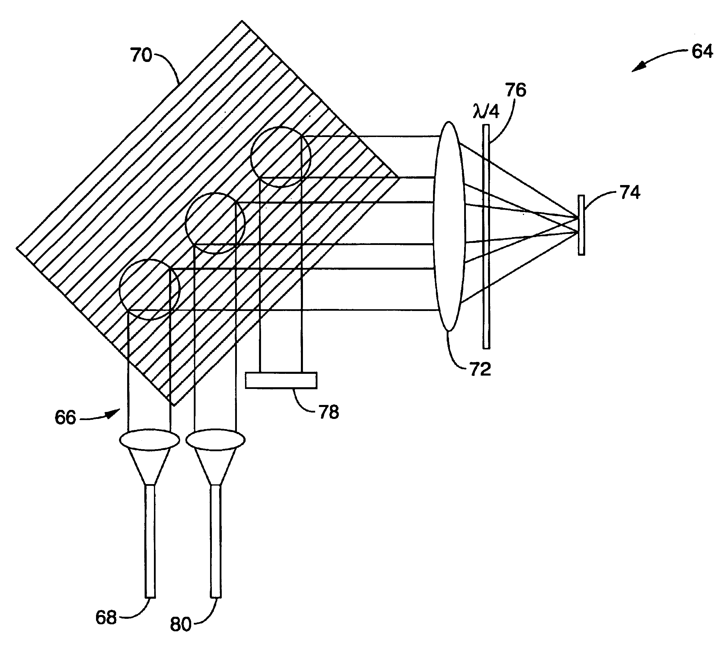
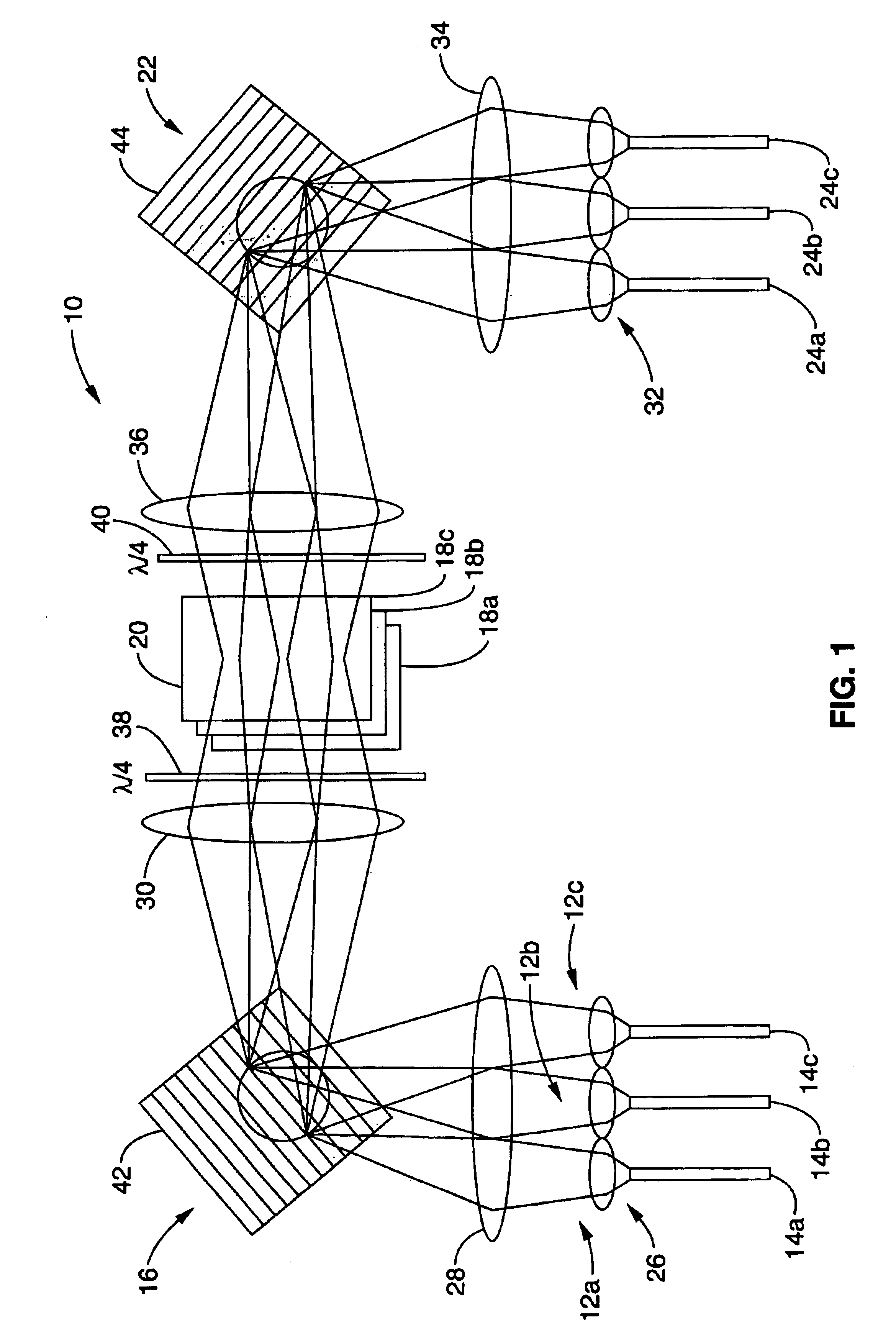
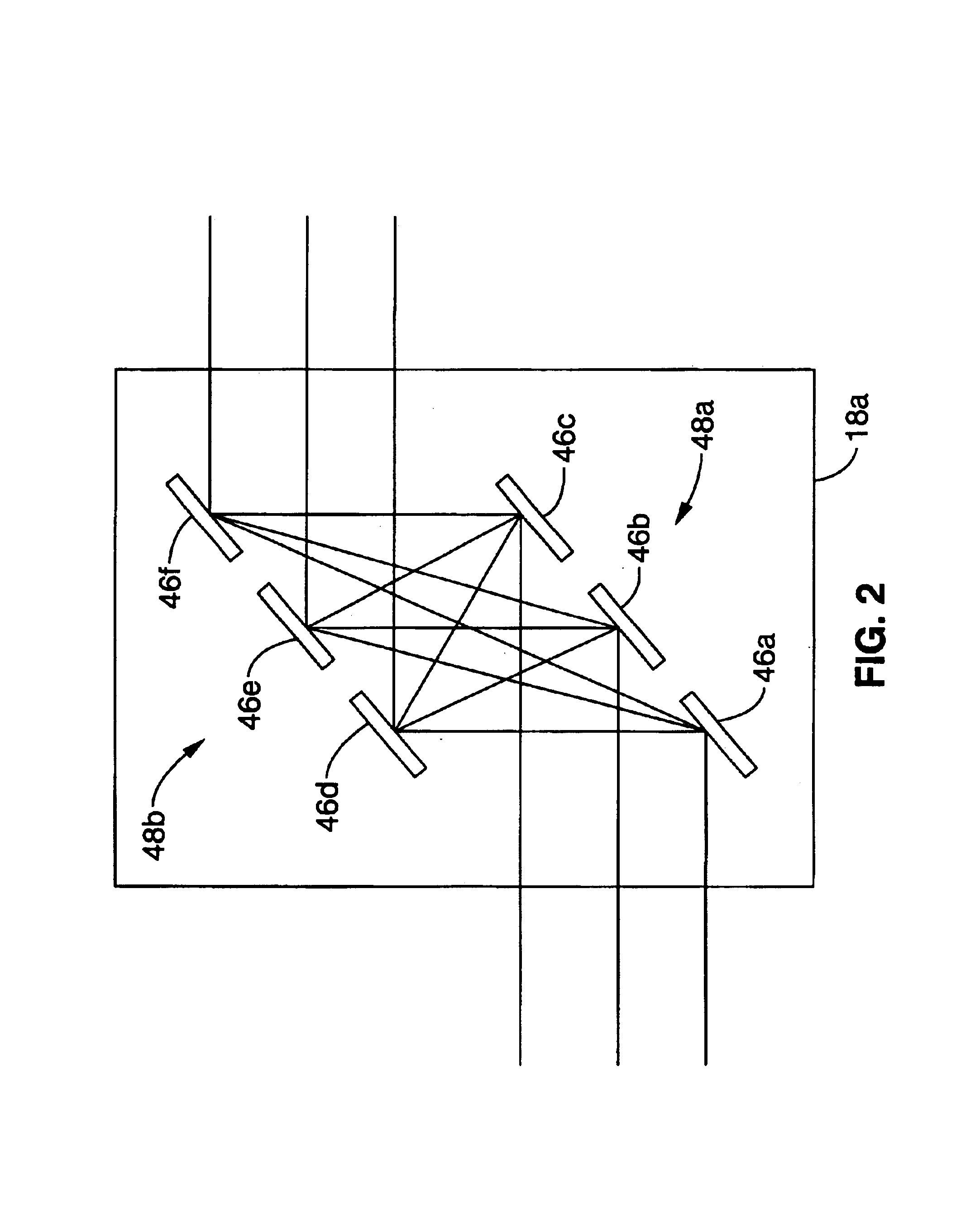
[0042]Referring first to FIG. 1, a multi-port (N×N ports), multi-wavelength (M wavelength) WDM cross-connect switch 10 embodying this invention is schematically shown where, in the example shown, N=3. In this switch 10, the wavelength channels 12a, 12b, 12c of three input fibers 14a, 14b, 14c are collimated and spatially dispersed by a first (or input) diffraction grating-lens system 16. The grating-lens system 16 separates the wavelength channels in a direction perpendicular to the plane of the paper, and the dispersed wavelength channels are then focused onto a corresponding layer 18a, 18b, 18c of a spati...


PUM


Abstract

A cross-connect switch for fiber-optic communication networks employing a wavelength dispersive element, such as a grating, and a stack of regular (non-wavelength selective) cross bar switches using two-dimensional arrays of micromachined, electrically actuated, individually-tiltable, controlled deflection micro-mirrors for providing multiport switching capability for a plurality of wavelengths. Using a one-dimensional micromirror array, a fiber-optic based MEMS switched spectrometer that does not require mechanical motion of bulk components or large diode arrays can be constructed with readout capability for WDM network diagnosis or for general purpose spectroscopic applications.

Description

CROSS-REFERENCE TO RELATED APPLICATIONS[0001]This application is a continuation of application Ser. No. 09 / 928,237 filed on Aug. 10, 2001 now abandoned, which is a continuation of application Ser. No. 09 / 618,320 filed on Jul. 18, 2000, now U.S. Pat. No. 6,289,145, which is a continuation of application Ser. No. 09 / 022,591 filed on Feb. 12, 1998, now U.S. Pat. No. 6,097,859, which claims priority from provisional application Ser. No. 60 / 038,172 filed on Feb, 13, 1997.[0002]This application is also related to application Ser. No. 09 / 748,025 filed on Dec. 21, 2000, now U.S. Pat. No. 6,327,398, application Ser. No. 09 / 766,529 filed on Jan. 19, 2001, now U.S. Pat. No. 6,389,190, application Ser. No. 09 / 780,122 filed on Feb. 8, 2001, now U.S. Pat. No. 6,374,008, co-pending application Ser. No. 09 / 813,446 filed on Mar. 20, 2001, and co-pending application Ser. No. 09 / 849,096 filed on May 4, 2001.STATEMENT REGARDING FEDERALLY SPONSORED RESEARCH OR DEVELOPMENT[0003]Not ApplicableREFERENCE TO...

Claims


Application Information

Patent Timeline
Patent Type & Authority Patents(United States)
IPC IPC(8): G01J3/28G02B6/35H04Q11/00G02B6/32
CPCG01J3/28G02B6/35G02B6/3516G02B6/3518G02B6/356G02B6/3592H04Q11/0005G02B6/32G02B6/3512G02B6/3534G02B6/3542G02B6/3546G02B6/3556G02B6/3566G02B6/357G02B6/3582G02B6/3584H04Q2011/0024H04Q2011/0026H04Q2011/0083
Inventor SOLGAARD, OLAVHERITAGE, JONATHAN P.BHATTARAI, AMAL R.
Owner RGT UNIV OF CALIFORNIA
Why Eureka
Try Eureka