Method and apparatus for leveling thermal stress variations in multi-layer MEMS devices

a technology of multi-layer mems and thermal stress variation, applied in the direction of instruments, optical elements, semiconductor/solid-state device details, etc., can solve the problems of the change of the pull-down voltage required to fully deflect the ribbon, and the inconvenient operation of the ribbon. achieve the effect of constancy of tension, reduced variations in deflection force, and constant operation over an operational temperature rang

Inactive Publication Date: 2005-07-26
SILICON LIGHT MACHINES CORP
View PDF880 Cites 20 Cited by
  • Summary
  • Abstract
  • Description
  • Claims
  • Application Information

AI Technical Summary

Benefits of technology

[0008]The present invention is directed to a method and apparatus for leveling the aggregate forces within a MEMS structure over an operational temperature range. The present invention is also directed to a method and apparatus for athermalizing a MEMS component to achieve a constancy of operation over an operational temperature range. The present invention is particularly adapted to athermalizing a ribbon in a grating light valve™ light modulator such that it maintains a constancy of tension over an operational

Problems solved by technology

However, the tension within the ribbon across the substrate does not remain constant over a range of temperatures.
This has a variety of undesirable eff

Method used


Image

  • Method and apparatus for leveling thermal stress variations in multi-layer MEMS devices
  • Method and apparatus for leveling thermal stress variations in multi-layer MEMS devices
  • Method and apparatus for leveling thermal stress variations in multi-layer MEMS devices

Examples


Embodiment Construction

[0035]U.S. Pat. No. 5,311,360 entitled “METHOD AND APPARATUS FOR MODULATING A LIGHT BEAM” and U.S. Pat. No. 5,841,579 entitled “FLAT DIFFRACTION GRATING LIGHT VALVE to Bloom et al. and U.S. Pat. No. 5,661,592 entitled “METHOD OF MAKING AN APPARATUS FOR A FLAT DIFFRACTION GRATING LIGHT VALVE” to Bornstein et al., and U.S. Pat. No. 5,808,797 entitled “Method and Apparatus for Modulating a Light Beam” to Bloom, et al. are herein incorporated by reference.

[0036]Reference will now be made in detail to the preferred embodiments of the invention, examples of which are illustrated in the accompanying drawings.

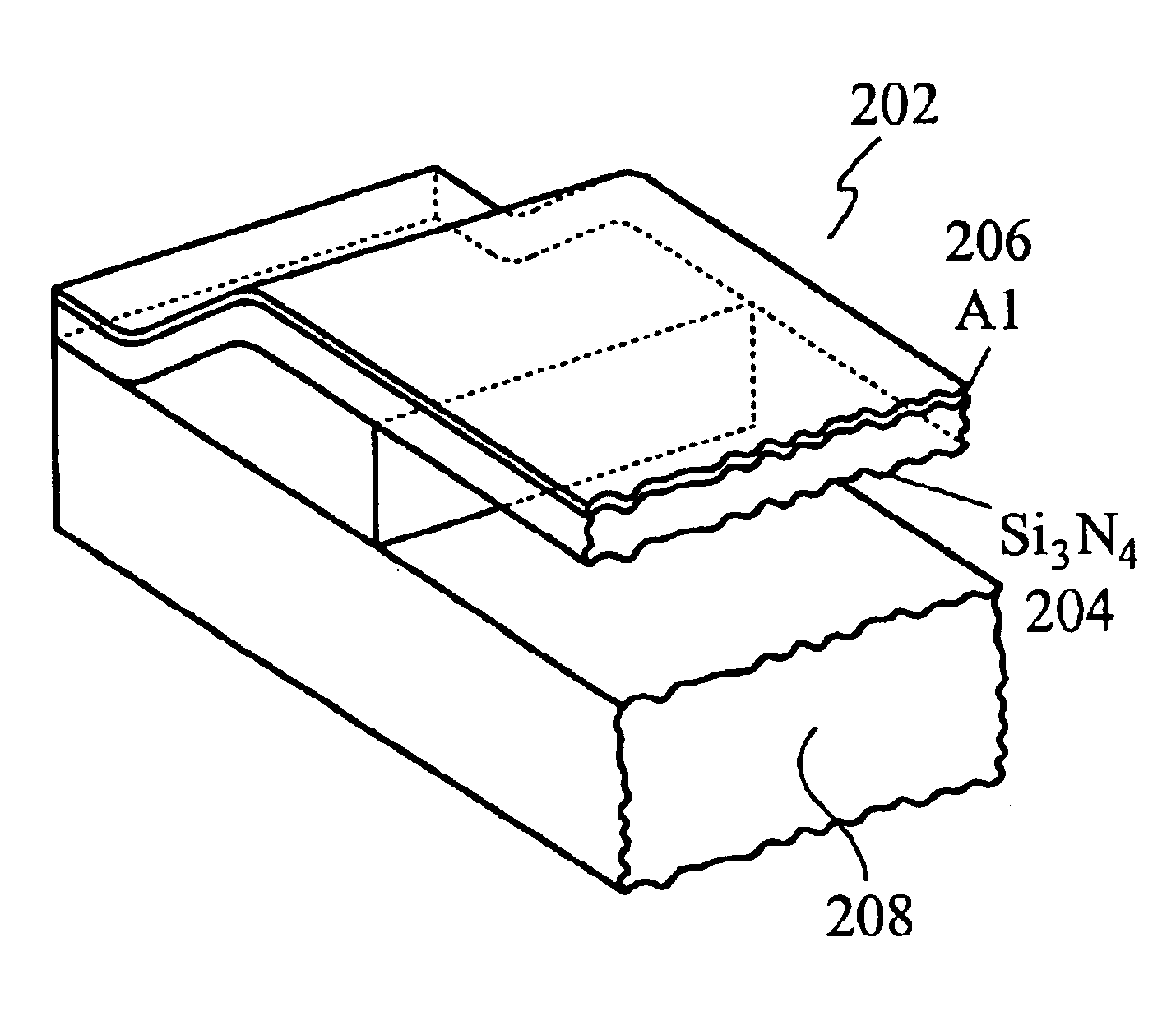
[0037]FIG. 7 is a cross sectional view of a ribbon 134. Arrows present in the layers 126, 128 illustrate that there can be distinct tensile and compressive forces present within the layers 126, 128 of the ribbon 134. Rather, the tension of the ribbon is equal to the sum of the tensions and compressions of the various layers, as illustrated in equation 1:

Fribbon=Σ(σAl+σSi3N4+σOx)  1)

In...


PUM

PropertyMeasurementUnit
Thicknessaaaaaaaaaa
Thicknessaaaaaaaaaa
Thicknessaaaaaaaaaa

Abstract

A MEMS device such as a grating light valve™ light modulator is athermalized such that the force required to deflect the movable portion of the MEMS device remains constant over a range of temperatures. In MEMS embodiments directed to a grating light valve™ light modulator, a ribbon is suspended over a substrate, and the ribbon tension is kept constant over a temperature range by adjusting the aggregate thermal coefficient of expansion of the ribbon to match the aggregate thermal coefficient of expansion of the substrate. Various opposition materials have an opposite thermal coefficient of expansion as the aluminum layer of a grating light valve™ light modulator ribbon, using the thermal coefficient of expansion of the substrate as a zero coefficient reference. The adjustment of the thermal coefficient of expansion of the ribbon can be performed variously by thickening existing layers of opposition material or adding additional layers of new opposition material to the ribbon, or reducing the aluminum in aluminum layer. The aluminum layer may be reduced variously by reducing the thickness of the aluminum layer, or reducing the surface area that the aluminum covers, or reducing both the surface area and the thickness. Embodiments may combine the reduction of aluminum with the use of opposition materials.

Description

FIELD OF THE INVENTION[0001]The present invention relates to the field of leveling thermal stress and tension variations which develop in MEMS devices comprised of different materials. More particularly, the present invention relates to leveling thermal stress variations within a MEMS device by manipulating the effective thermal coefficient of expansion related stress variations over temperature in a first layered member to approximate the effective thermal coefficient of expansion related stress variations over temperature of a second layered member.BACKGROUND OF THE INVENTION[0002]MEMS technology involves the process of designing and building micro-sized mechanical and / or electrical structures with technology generally developed for 5V CMOS processes common to IC fabrication. In one area of MEMS device fabrication, typically referred to as surface micro-machining, layers of semiconductor, metal, and insulator materials are utilized to build structures which can be activated by ele...

Claims


Application Information

Patent Timeline
IPC IPC(8): G02B26/08B81B3/00B81C1/00
CPCB81C1/00666G02B26/0808B81B2203/0109B81C2201/0167
Inventor DE GROOT, WILHELMUSMAHESHWARI, DINESH
Owner SILICON LIGHT MACHINES CORP
Why Eureka
Try Eureka