System and method for kinematic consistency processing

a kinematic consistency and flight data technology, applied in process and machine control, instruments, navigation instruments, etc., can solve the problems of generating errors, introducing artificial oscillations not present in original data, and spiking data at angular rates, so as to improve accuracy and reliability of corrected flight data and increase analytical results confiden

Inactive Publication Date: 2005-07-26
THE BOEING CO
View PDF4 Cites 9 Cited by
  • Summary
  • Abstract
  • Description
  • Claims
  • Application Information

AI Technical Summary

Benefits of technology

[0016]A system, method, and computer program product for analyzing flight test and FDR data that overcomes technical difficulties associated with traditional flight data analysis methods. The present invention strictly follows physics laws without compromising the complexities of aircraft dynamics or relying on manual iteration or subjective user's experiences. As a result, the present invention enhances accuracy and reliability of corrected flight data, providing more accurate flight simulation model development and increased confidence of analytical results for accident / incident investigations.

Problems solved by technology

Aircraft position, speed and acceleration (or load factor) data measured from different instruments usually contain measurement errors from sensors, transducers or data acquisition systems.
The resulting angular rates produce spiky data due to sparse and / or noisy data initially incorporated in the Euler angles.
As such, in addition to limitations associated with its subjective implementation, it inherently generates errors that can cumulate when integrated for Euler angles, and can also introduce artificial oscillations not present in the original data.
However, accelerometers that measure the load factors suffer from inherent errors that must be corrected to avoid misleading results due to integrations.
Two principal accelerometer errors are (1) the error due to the accelerometer location not coinciding exactly with the center of gravity (CG), and (2) the error due to accelerometer offsets or biases.
The magnitude of the error due to the accelerometer location not coinciding with the CG is typically small, but may be significant.
The bias error, on the other hand, is likely very significant because even a small offset will generate large errors when integrated over time.
The load factors reported by the accelerometers are rarely the actual load factors at the accelerometer location because the sensor is not calibrated perfectly.
The biases must be accounted for because even small errors in load factor data will produce very large errors in speed and position calculations when integrated over time.
For flight maneuvers such as banked turns and stalls the method fails to produce a reliable and consistent correction for the entire maneuver.
For the same reason the method is also not adequate for analyzing FDR data recorded during aircraft accidents / incidents.
These integrated positions are compared to the inertial positions calculated previously, and an error is calculated.
For example, NTSB process is laborious and not repeatable with different users because each user must rely on subjective judgment to modify the bias error during the iterative process.
This approach magnifies computational difficulties associated with equation couplings and integration.
Moreover, because the approach relies heavily on subjective experience, the accuracy and reliability of data correction are significantly diminished.
In addition, with the NTSB process, it is mathematically difficult to reconstruct time-varying load factors if less than the basic required linear data is available.
The accuracy of current wind analyses is suboptimal due to their reliance on the results of inferior rotational and translational kinematic consistency analyses, as described above.
In addition, current wind analyses do not accurately evaluate the impact of aircraft sideslip.

Method used


Image

  • System and method for kinematic consistency processing
  • System and method for kinematic consistency processing
  • System and method for kinematic consistency processing

Examples


Embodiment Construction

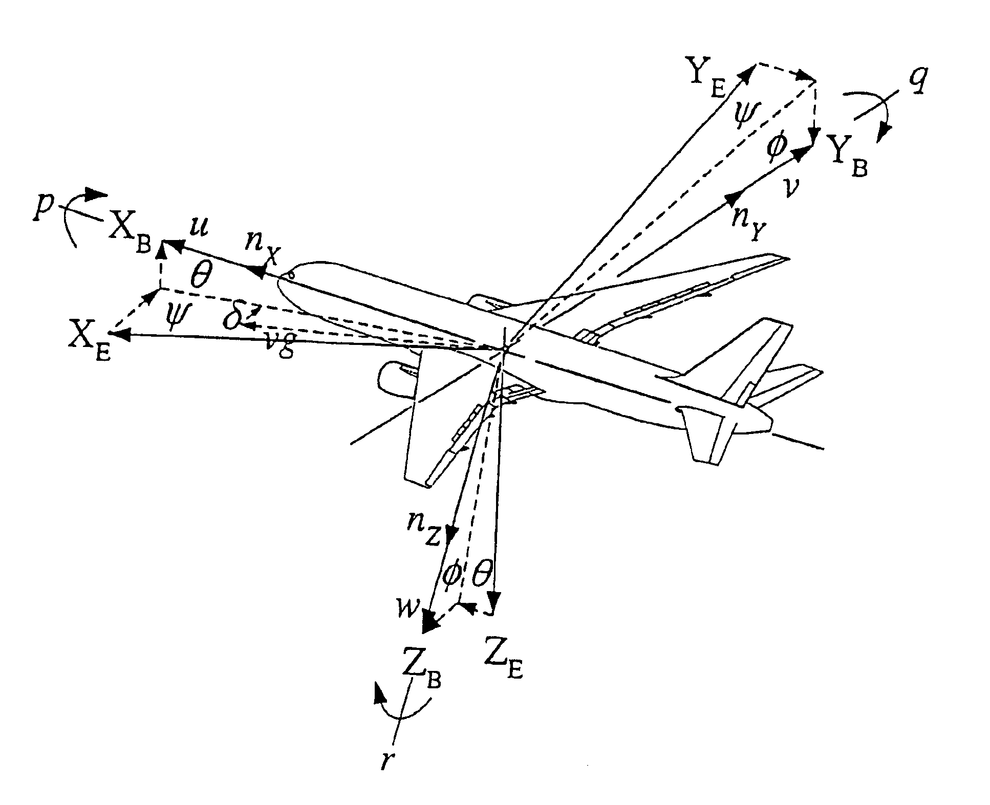
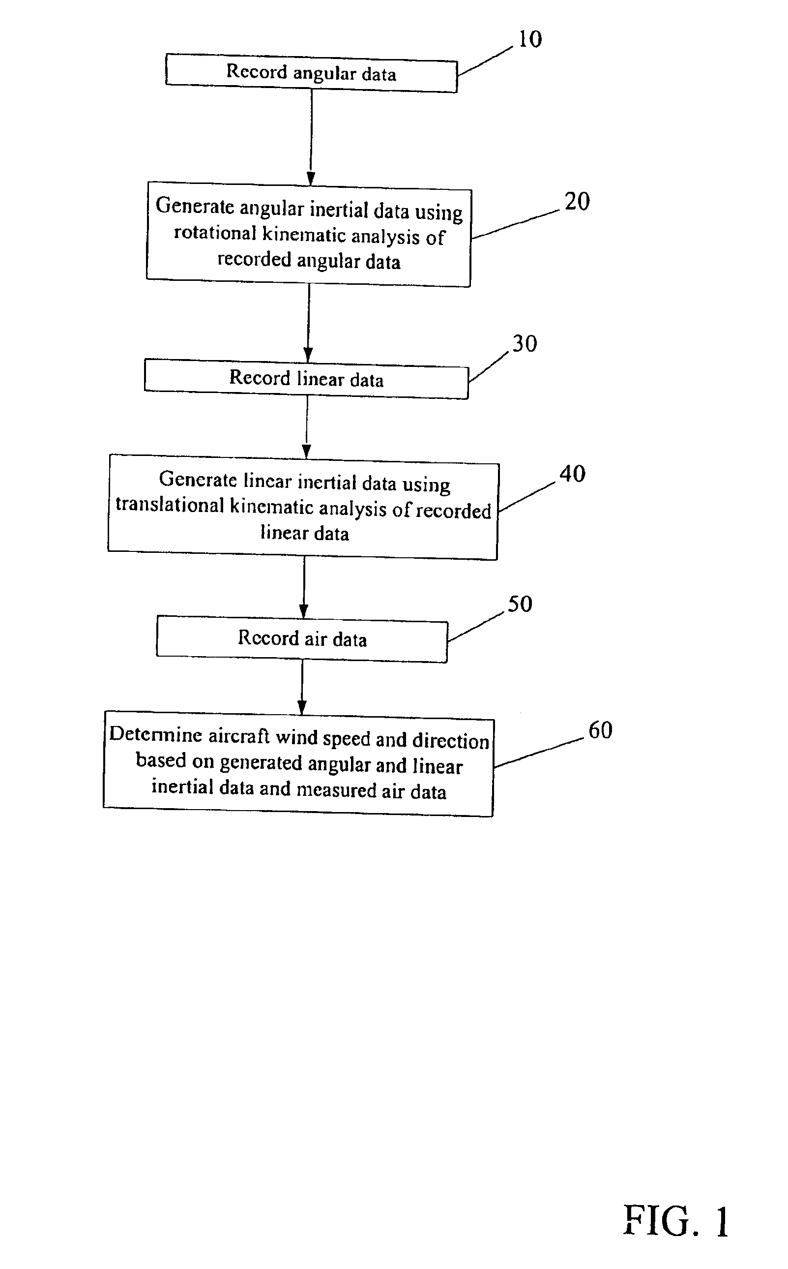
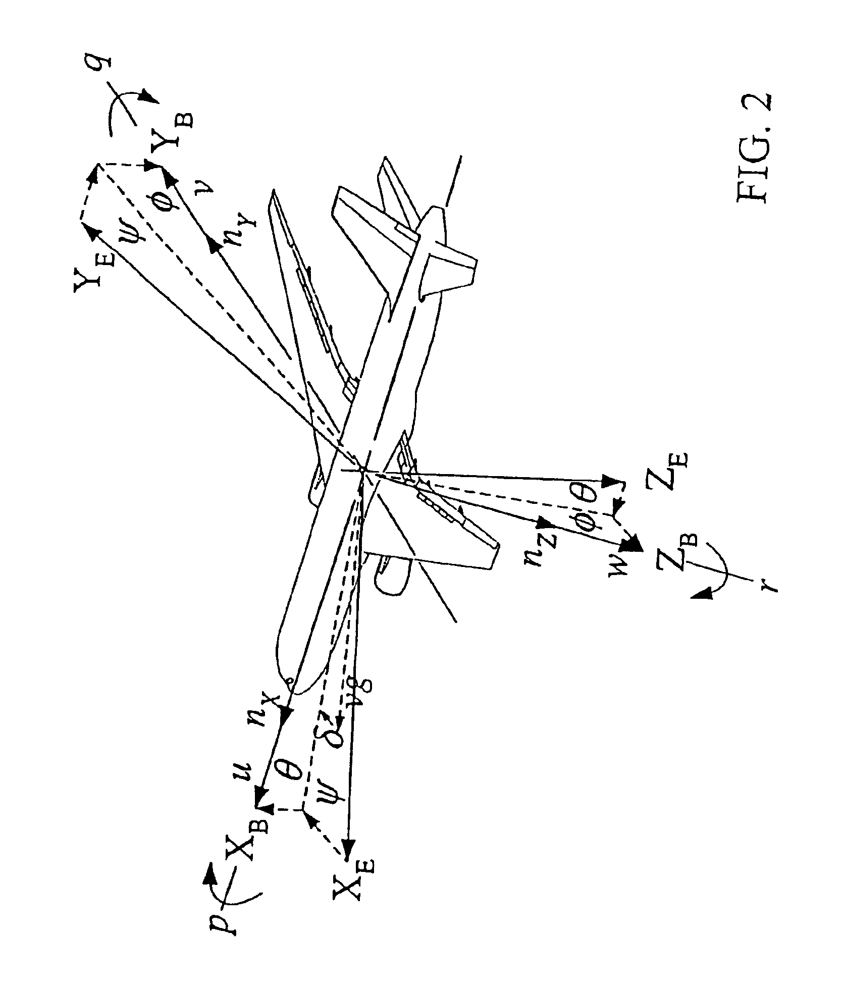
[0027]The present invention provides a system and method for processing flight test and Flight Data Recorder (FDR) data to ensure that measured aircraft position, speed and acceleration (or load factors) data are kinematically consistent and compatible. In a preferred embodiment, the present invention initially performs a rotational kinematic analysis to determine the kinematically consistent angular rates and acceleration, as well as more accurate Euler angles associated with an aircraft's rotational movement. Using the results of the rotational kinematic consistency analysis, a translational kinematic consistency analysis is performed. This produces kinematically consistent load factors and inertia! speed associated with the aircraft's translational movement, as well as more accurate altitude, ground speed and drift angle data. The inertial data generated from these two analyses are combined with recorded air data to calculate wind speed and direction.

[0028]An overview of the meth...


PUM


Abstract

A system, method, and computer program product for analyzing flight test and FDR data that overcomes technical difficulties associated with traditional flight data analysis methods. The method includes inputting angular, linear data and recorded air data, where angular data may include Euler angles or angular rates and linear data may include altitude, ground speed, airspeed, drift angle, runway excursion or load factors. The method generates first inertial data using optimal control to minimize the objective function associated with the angular data and second inertial data using optimal control to minimize the objective function associated with the linear data. The method determines wind speed and direction based on the first and second generated inertial data and the air data.

Description

PRIORITY CLAIM[0001]This application is a divisional of U.S. patent application Ser. No. 10 / 329,074 filed Dec. 24, 2002 now U.S. Pat. No. 6,772,080.FIELD OF THE INVENTION[0002]This invention relates generally to aircraft flight data processing and, more specifically, to a system and method for kinematically correcting flight data.BACKGROUND OF THE INVENTION[0003]Rigid aircraft motion while airborne is described by complex six degrees of freedom (6-DOF) dynamics. An aircraft, while in the air, is free to move in six degrees of freedom. The aircraft can rotate about any of its three axes x, y and z. The corresponding rotational or angular velocities are labeled as p (roll rate), q (pitch rate) and r (yaw rate), respectively. The aircraft can also translate along any of its three axes x, y, and z. The corresponding translational or linear velocities are identified as u (forward velocity), v (side velocity) and w (up or down velocity), respectively.[0004]Rotational and translational air...

Claims


Application Information

Patent Timeline
Patent Type & Authority Patents(United States)
IPC IPC(8): B64C1/00G06F19/00G06F7/00G05D1/08
CPCG05D1/0825
Inventor LUO, JIA
Owner THE BOEING CO
Why Eureka
Try Eureka