
Method and apparatus for the lifting of offshore installation jackets

a technology for installation jackets and equipment, which is applied in the direction of marine vessel transportation, caissons, artificial islands, etc., can solve the problems of difficult turning, insufficient strength to transfer its own weight, and relatively weak design or constructions in transversal directions, etc., to achieve low fabrication costs, simple unloading, and cost-effective

Inactive Publication Date: 2005-08-02
VATSV ANG G JAN
View PDF6 Cites 12 Cited by
  • Summary
  • Abstract
  • Description
  • Claims
  • Application Information

AI Technical Summary

Benefits of technology

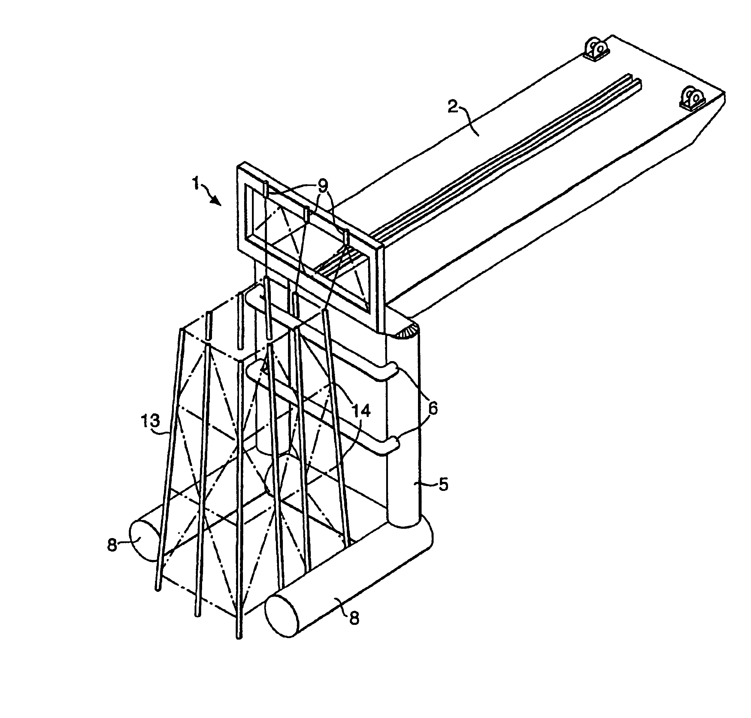
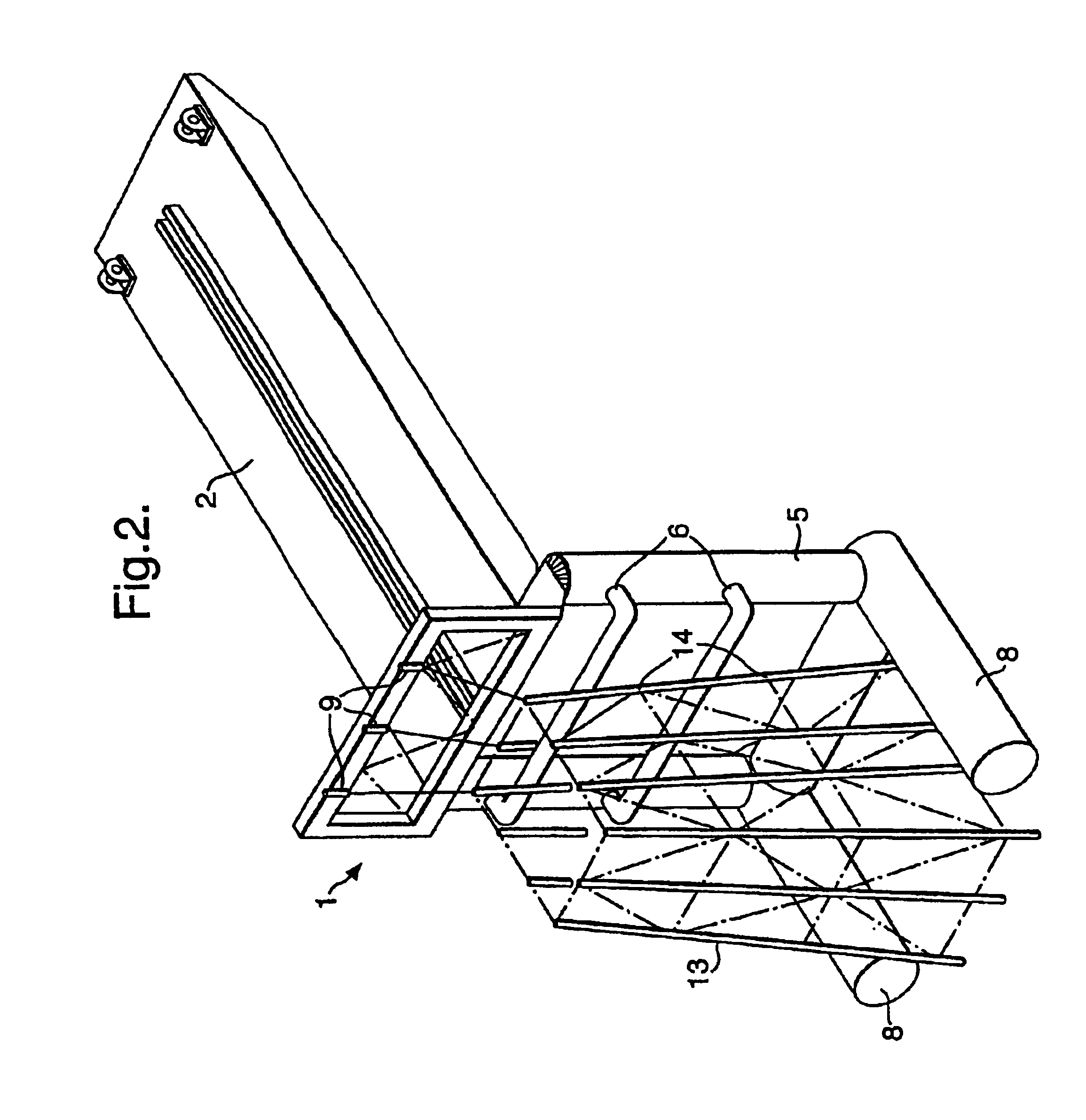
[0020]The load on the construction at the top of the arm is reduced as the weight of the jacket is transferred to the arm. At the end, the jacket will lie on the arm in a substantially horizontal position. The lifting construction according to the invention is built with sufficient strength and buoyancy to lift platform jackets.
[0025]The ballast system is designed such that each tank can be filled and emptied separately. Ballasting is performed by means of submerged pumps or pressurized air. Pumps and valves are controlled from the vessel, and alternatively from a supporting vessel. Ballasting should preferably be performed such that a controlled load is applied to the joint and such that it is ensured that the arm is pivoting in the right direction as compared to the vessel during rising. The branches could for instance, during rising, be ballasted first, such that the point of attack or point of application of the buoyancy creates a rotating force or moment about the joint such that the arm is turned the correct way during rising. When the arm has turned a certain angle as compared to the horizontal in this way, ballast tanks in a lower tubular transversal section can be emptied, succeeding emptying of the ballast tanks in the longitudinal tubes.
[0027]The advantages with the invention is that it results in a low fabrication cost, no activities under water, except for cutting off or in any other way releasing the jacket from the foundation, and securing the jacket above the waterline. The invention can be adapted to all steel jackets, be secured to all barge sizes, and does not normally require being adapted to different barges, with possibly the exception of the pivoting joint, where the skidding rail must be installed. This results in a quick, simple, safe and thereby cost effective removal method, with a simple unloading.

Problems solved by technology

As offshore oilfields throughout the world are being depleted, and when further exploitation no longer is profitable, platforms will have to be decommissioned or shut down.
These designs or constructions are relatively weak in a transversal direction and do not have sufficient strength to transfer its own weight without many supporting points, localized on the joints or nodes between the legs and the transversal supports.
However, it is a problem that such jackets frequently are difficult to turn, and this means that they often have to be cut into smaller parts for transport to the shore.
The conventional lifting vessels have a limited lifting capacity, and the use of such requires a lot of under water work.
Transferring the jacket to a barge for transport to the shore also requires calm weather conditions with low wave heights, something that possibly lengthens these operations and thereby makes them more financially demanding.
The building of new vessels is however fairly expensive and necessitates many marine systems in addition to fabrication of steel material.
By integrating these additional services in the lifting vessel, the need for additional vessels during the preparation offshore will be limited.

Method used


Image

  • Method and apparatus for the lifting of offshore installation jackets
  • Method and apparatus for the lifting of offshore installation jackets
  • Method and apparatus for the lifting of offshore installation jackets

Examples


Embodiment Construction

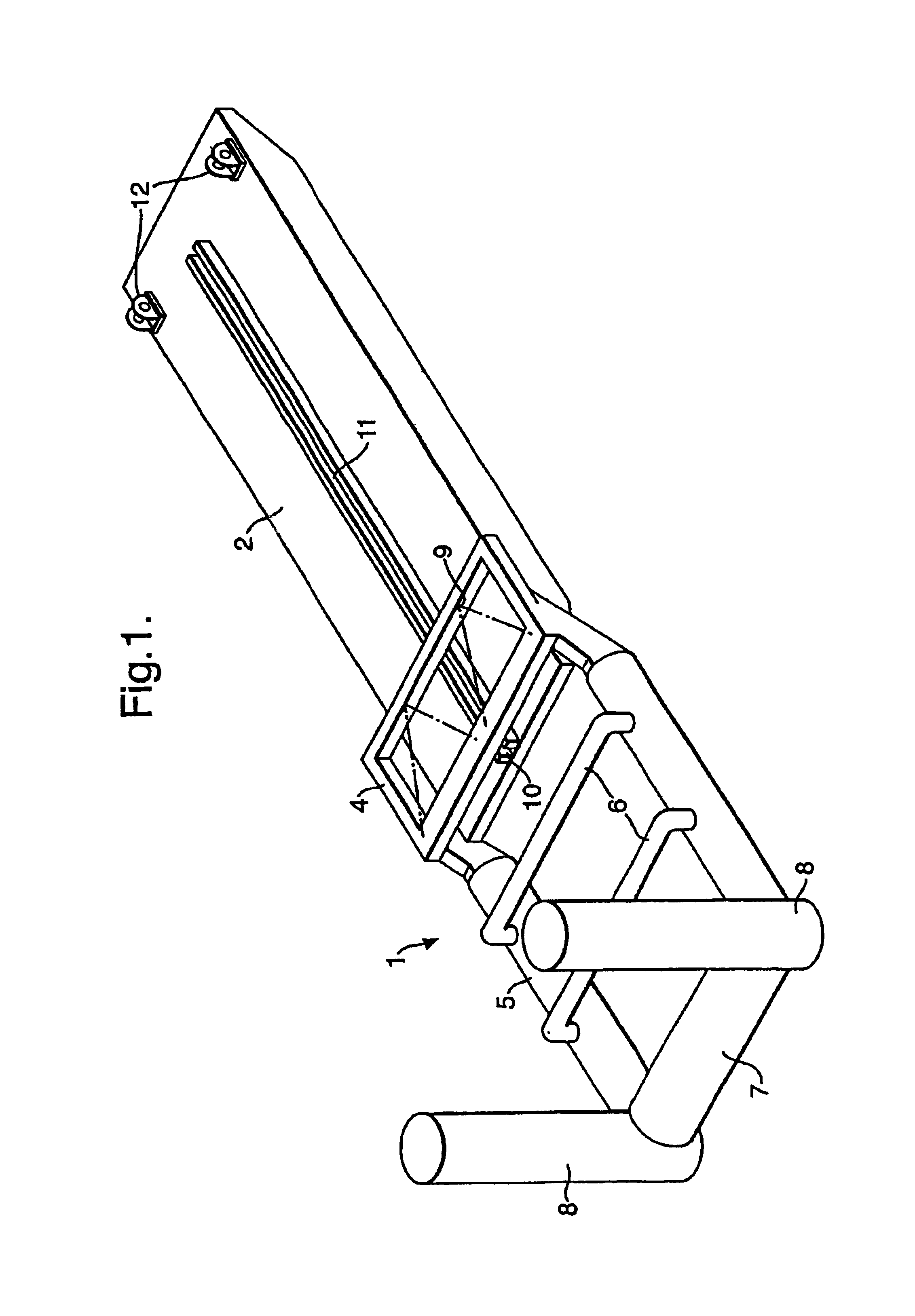
[0040]FIG. 1 to FIG. 4 shows an embodiment of an offshore lifting construction or arm (1) according to the invention. The figures show various phases of a lifting process. The lifting construction is shown attached to a barge (2). The lifting construction is designed with two substantially parallel longitudinal elements or tubes (5), between, on the upper part of the lifting construction provided, a frame (4) with a holding arrangement (9) for the jacket that is to be lifted, two intermediate supporting elements or beams (6), a lower tubular transversal unit (7) and a joint (10) for attachment to the barge (2). On the lower part of the two substantially parallel longitudinal elements (5), two tubular elements or branches (8) are provided substantially perpendicular to the longitudinal direction of the substantially parallel longitudinal elements (5). The barge is equipped with a skidding rail (11) and winches (12). The joint (10) (shown on FIG. 1 and FIG. 11) is skiddingly connected...


PUM


Abstract

An offshore lifting construction is able to control buoyancy for the lifting of jackets for offshore platforms. The lifting construction is designed such that it can be ballasted for raising and lowering and such that it can take several positions. The lifting construction is designed as an arm equipped with a joint for attachment to a vessel. The arm includes two substantially parallel longitudinal elements with intermediate supporting elements. One of the ends of the arm includes at least two tubular branches substantially perpendicular to the longitudinal direction of the substantially parallel longitudinal elements. At least one of the elements of the arm includes at least one ballastable tank. The arm is equipped with device for attachment to the jacket that is to be lifted. A method for rising jackets or jacket legs for offshore platforms is also described.

Description

BACKGROUND OF THE INVENTION[0001]1. Field of the Invention[0002]The invention concerns vessels for lifting heavy loads offshore, and particularly vessels for removing offshore platforms with steel jackets, after the platform deck is removed for instance by means of another lifting vessel. A method for using such vessels is also enclosed.[0003]2. Description of Related Art[0004]As offshore oilfields throughout the world are being depleted, and when further exploitation no longer is profitable, platforms will have to be decommissioned or shut down. It is required from various authorities and international cooperation treaties (OSPAR Convention decision 3 / 98 and the Guidelines of the Maritime Organization IMO) that all platforms that have been taken out of service, and that can be removed, shall be brought onshore for removal.[0005]On the Ekofisk field alone, soon 15 platforms will be decommissioned and removed. Most of these platforms include a steel jacket on the seabed with a platfo...

Claims


Application Information

Patent Timeline
Patent Type & Authority Patents(United States)
IPC IPC(8): B63B35/00E02B17/00
CPCB63B35/003E02B17/00E02B2017/0047E02B2017/0052
Inventor VATSV.ANG.G, JAN
Owner VATSV ANG G JAN
Learn More