
Neutron detector

Inactive Publication Date: 2005-08-02
CONSTELLATION TECH
View PDF21 Cites 43 Cited by
  • Summary
  • Abstract
  • Description
  • Claims
  • Application Information

AI Technical Summary

Benefits of technology

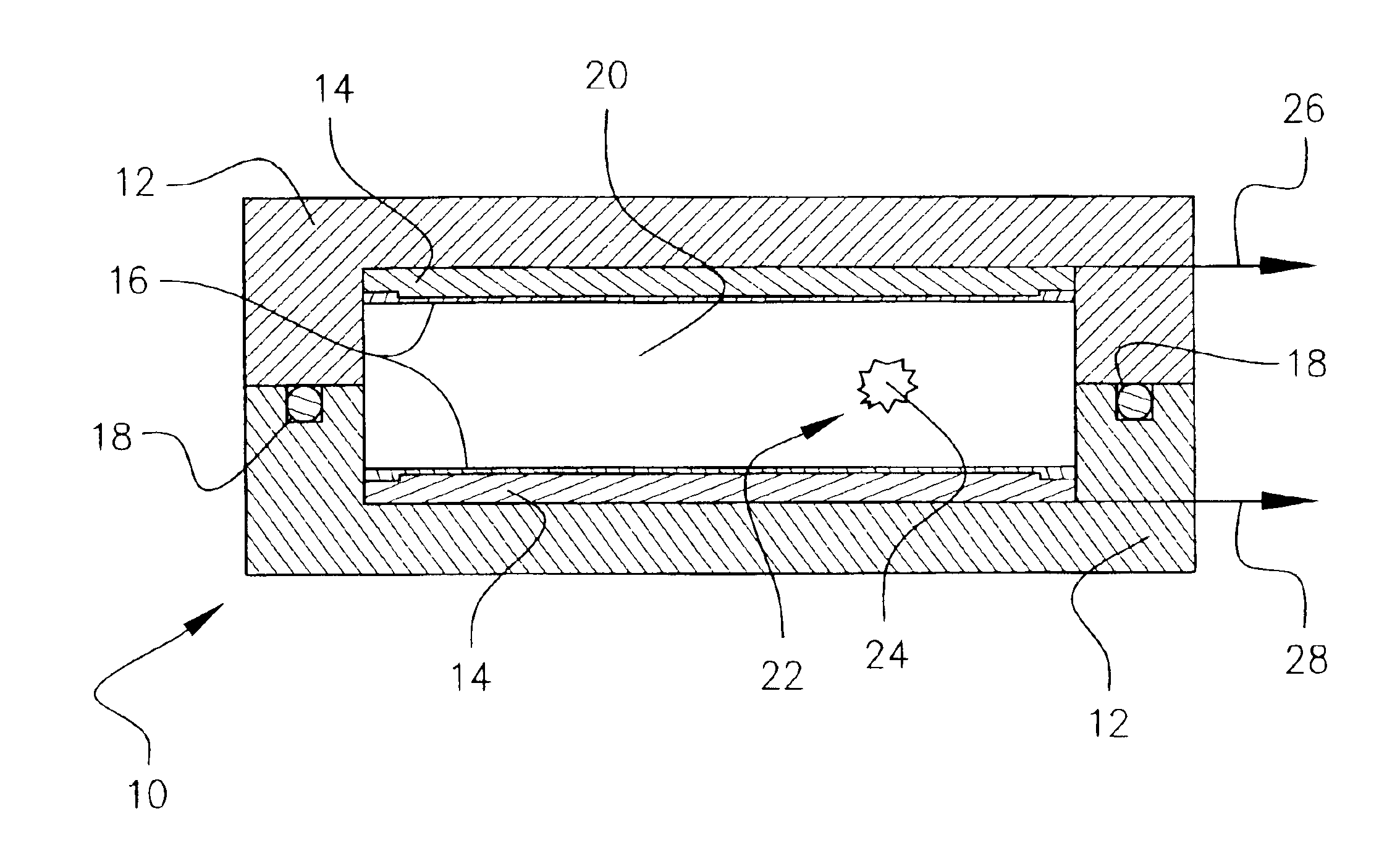
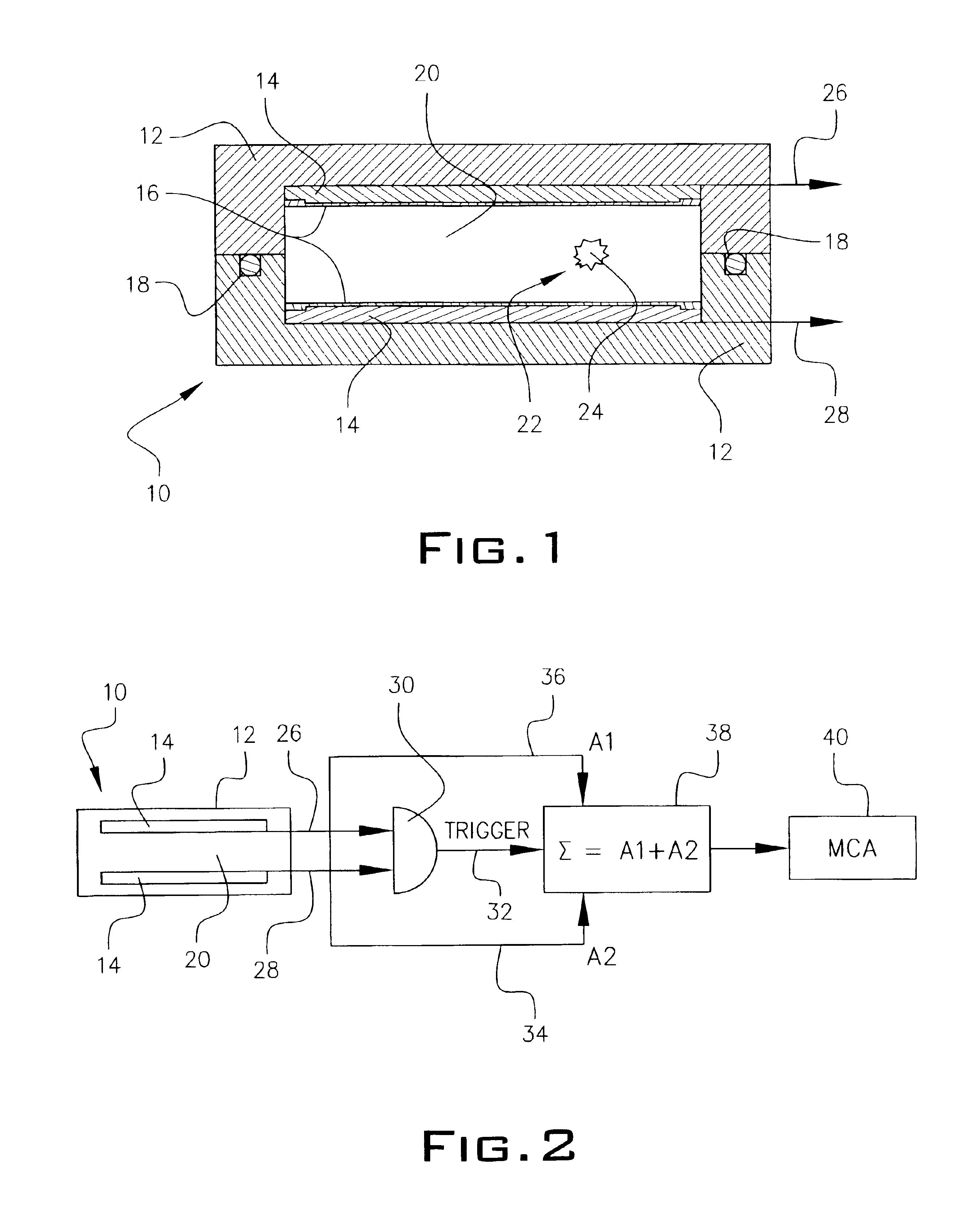
[0010]The present invention solves the problem by providing a device for efficiently measuring neutron radiation with increased sensitivity. The device can measure both thermal and fast neutrons. The detector has at least two photodetectors working in coincidence forming a gap in between the photodetectors. A substance that permits scintillation in the absorption of neutron radiation is disposed within the gap. A sealed shell can be used to enclose the photodetectors if the substance to be used is a pressurized gas. If a condensed substance is used, no shell would be required. In the embodiment utilizing a gas substance, the shell could be constructed from carbon-fiberglass or aluminum. An example of a pressurized gas that can be employed includes, but is not limited to, 3He gas under pressure of about 20 bar. There is no need to apply an electric field within the gap. In the case of thermal neutrons, they can be absorbed by the 3He gas thereby producing a proton, a triton and visible light energy that is measured with the photodetectors.

Problems solved by technology

That makes the technique complicated and sensitive to calibration procedure.
There is another method of measuring thermal neutron fluxes for nuclear monitoring purposes with gas proportional counters but these detectors are sensitive to gamma ray background and have relatively low efficiency in pocket-size configurations.
In these detectors, the gas (3He or BF3) is limited in pressure by a few atmospheres because of low electron-ion yield from tracks of decay protons or alpha-particles and technical limitations in the application of sufficiently high voltage for effective charge application in the pressurized gases.
This detector is undesirably bulky and sensitive to gamma ray background.

Method used


Image

  • Neutron detector
  • Neutron detector
  • Neutron detector

Examples


Embodiment Construction

[0016]Throughout the following detailed description, the same reference numerals refer to the same elements in all figures.

[0017]The neutron detector 10 of FIG. 1 is a small and compact detector having a high sensitivity for use in detecting thermal neutrons. Such a device could be constructed as a pocket sized detector for use by individuals. Detector 10 improves the rejectability that is often seen in prior art devices which are unable to delineate gamma radiation from neutron radiation. In the case where a gas substance is used within detector 10 (to be discussed in further detail hereinafter) an outer pressure-tight closed container (or shell) 12 pervious to transmission therethrough of neutrons in the thermal energy region is employed. The container or shell 12 can be made from aluminum, carbon-fiberglass or other material exhibiting a low neutron absorption. Shell 12 can be a few inches long so it can be hand held or be constructed as a larger unit depending on its application...


PUM


Abstract

A neutron detector is provided which is able to measure thermal neutron radiation within a gap filled with a substance that permits scintillation in the absorption of thermal neutron radiation, the gap being formed between at least a first and second spaced apart photodetector working in electrical coincidence. The substance disposed within the gap can be either a gas, liquid or solid. In the case of a gas, a shell is used so that the gas can be retained and kept under pressure. The neutron detector is able to differentiate between gamma radiation and neutron energy. An alternate embodiment of the novel detector includes a device which employs a plurality of detectors surrounding a moderator which can be used to measure both thermal and high energy neutrons.

Description

GOVERNMENT LICENSE RIGHTS[0001]This invention was made with U.S. Government support under contract or grant DTRA01-99-C-0187 awarded by the U.S. Department of Defense, Defense Threat Reduction Agency. The U.S. Government has certain rights in the invention.BACKGROUND OF THE INVENTION[0002]1. Field of the Invention[0003]This invention relates to neutron detectors. More specifically, it refers to a neutron detector capable of measuring neutron radiation wherein at least two photodetectors are employed, spaced apart by a gap between them wherein a substance is disposed which permits scintillation in the absorption of neutron radiation thereby permitting the detector to differentiate neutron radiation from gamma radiation.[0004]2. Description of the Prior Art[0005]Neutron detectors are known in the prior art. Real time personal neutron detectors are required, to name a few examples, for occupational radiation protection at nuclear power plants, nuclear material processing facilities, hi...

Claims


Application Information

Patent Timeline
IPC IPC(8): G01T3/00G01T3/06H01S1/00
CPCG01T3/00G01T3/008G01T3/06
Inventor BOLOZDYNYA, ALEXANDER I.RICHARDS, JOHN D.ARODZERO, ANATOLI
Owner CONSTELLATION TECH
Learn More