Enhancing polarized light microscopy

a polarized light and microscopy technology, applied in the field of polarized light, can solve the problems of inordinately long measurement time, subject to errors, and relatively fast method

Inactive Publication Date: 2005-08-02
MARINE BIOLOGICAL LAB
View PDF10 Cites 131 Cited by
  • Summary
  • Abstract
  • Description
  • Claims
  • Application Information

AI Technical Summary

Benefits of technology

[0014]In another aspect of the invention, an optical system includes a spatial light modulator having an aperture that is divided into at least two sectors. The light attenuation and / or propagation direction is affected by each sector. For example, an optical system may include a polarizer, a sectored variable retarder followed by another polarizer. Said sectored variable retarder plate sandwiched between two polarizers can serve as a means to control the amount of light passing through different regions of the second polarizer.

Problems solved by technology

This method is relatively fast, but may be subject to errors from variations in light intensities that stem from other sources than birefringence, e.g., light scattering or shading.
Furthermore, rapid measurements are restricted to a single image point or single area that exhibits uniform birefringence or other form of optical anisotropy, while measurements comparing several image points take an inordinately long time.
Neither method is compatible with biological specimens which typically require immersion objectives for high resolution imaging (which is incompatible with the universal rotation stage) and which include many birefringent structures that are too faint to observe conoscopically.
In addition, with regard to industrial applications such as rock and soil analysis for oil exploration, a typical analysis of rock samples with a polarizing microscope is a labor-intensive process yielding the orientation of one micro-crystal at a time.
Polarization distortions may result from reduced extinction caused by a high numerical aperture objective and condenser lenses of the microscope optics.

Method used


Image

  • Enhancing polarized light microscopy
  • Enhancing polarized light microscopy
  • Enhancing polarized light microscopy

Examples


Embodiment Construction

Systems

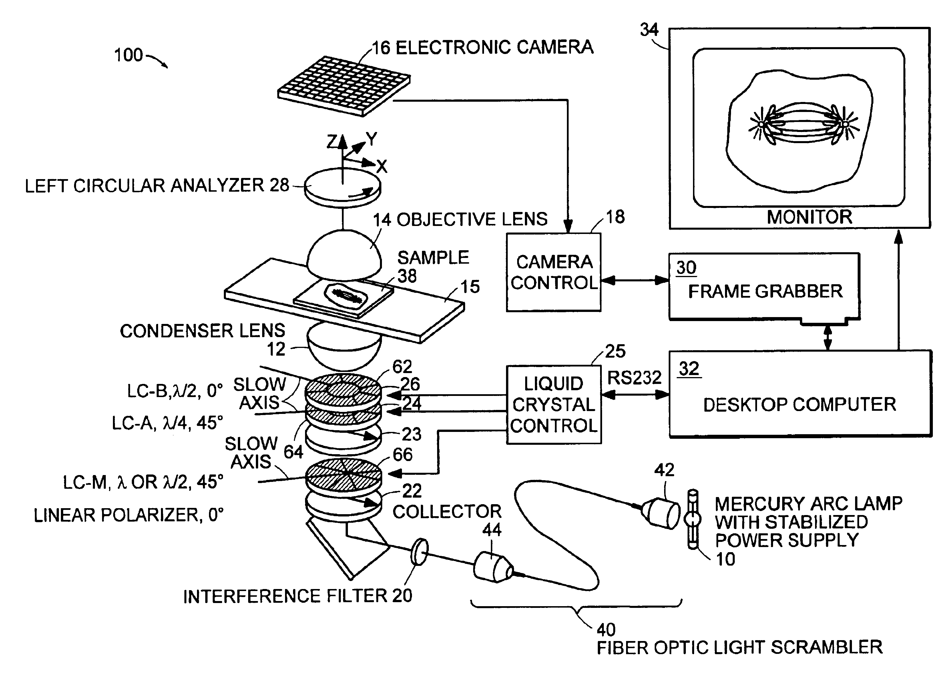
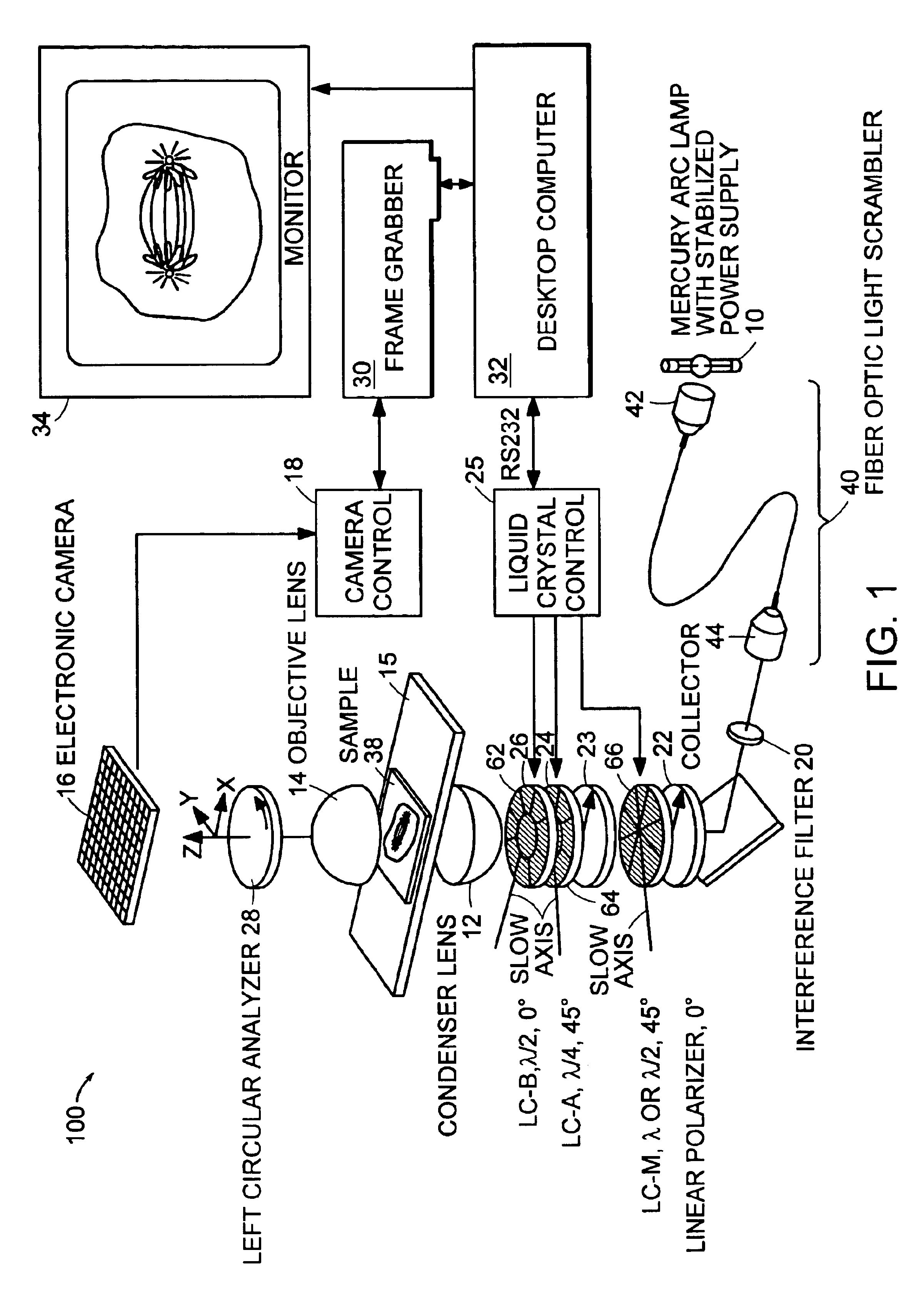
[0040]FIG. 1 illustrates an example 100 of an enhanced pol-scope of the present invention which includes sectored components as described below. The enhanced pol-scope of FIG. 1 is built using a conventional optical microscope such as a Zeiss Axiovert 200. In at least one embodiment, the enhanced pol-scope has, in addition to enhanced components as described below, one or more components that are described in U.S. Pat. No. 5,521,705 to Oldenbourg, et al., entitled “Polarized light microscopy” (“the '705 patent”). As described in the '705 patent, the conventional microscope includes a mercury arc lamp 10, a condenser lens 12, and an objective lens 14 (e.g., a 100×1.30-NA Plan Neofluar objective lens) on opposite sides of a specimen 38 on slide 15. The light from a specimen is directed to a video CCD camera 16 which provides signals to camera control 18 (e.g., a Dage-MTI model CCD-300).

[0041]As described below, the enhanced pol-scope includes enhancements to electro-optical com...


PUM


Abstract

A microscope system for determining optical properties of a specimen includes a source of polarized light, a detector for detecting the intensity of light incident thereon, an optical path extending from the source to the detector, a condenser for providing light from the source to the specimen, an objective for receiving light from the specimen, a support for mounting the specimen, a sectored variable retarder mounted in the optical path, and a polarized light analyzer mounted in the path between the sectored variable retarder and the detector. The variable retarder has a multiple sectors. Each sector is individually addressable by a control signal that affects the light retardation characteristics of the sector.

Description

CROSS-REFERENCE TO RELATED APPLICATION[0001]This application claims the benefit of U.S. Provisional Application Ser. No. 60 / 379,967 entitled “APERTURE SCANNING DEVICE” filed on May 13, 2002, which is incorporated herein by reference in its entirety.GOVERNMENT SUPPORT[0002]This invention was supported, in whole or in part, by grant GM 49210 from the National Institutes of Health. The government has certain rights in the invention.BACKGROUND OF THE INVENTION[0003]This invention relates to polarized light and, more particularly, to enhancing polarized light microscopy.[0004]A polarized light microscope system (“pol-scope”) has the ability to measure submicroscopic subjects such as molecular arrangements dynamically and non-destructively, e.g., in living cells and other specimens. For at least this reason, the pol-scope has been widely used in biological research, as described in U.S. Pat. No. 5,521,705 to Oldenbourg, et al., entitled “Polarized light microscopy”, (“the '705 patent”) wh...

Claims


Application Information

Patent Timeline
Patent Type & Authority Patents(United States)
IPC IPC(8): G02B21/00
CPCG02B21/0004G02B21/0092
Inventor OLDENBOURG, RUDOLFSHRIBAK, MYKHAILOHOYT, CLIFFORD C.TOROK, PETER
Owner MARINE BIOLOGICAL LAB
Why Eureka
Try Eureka