Long period chiral fiber grating apparatus

a technology of chiral fiber and grating apparatus, which is applied in the direction of force measurement by measuring optical property variation, instruments, heat measurement, etc., can solve the problems of limiting the length of the resulting grating, attenuating the transmitted fiber mode, and limiting the index contrast produced

Inactive Publication Date: 2005-08-02
CHIRAL PHOTONICS
View PDF6 Cites 30 Cited by
  • Summary
  • Abstract
  • Description
  • Claims
  • Application Information

AI Technical Summary

Benefits of technology

[0013]Another advantage of the LPCFG is that unlike conventional long period gratings, it is polarization sensitive—one circular polarized wave is coupled to the cladding mode more strongly than the wave of the other polarization. This enables the LPCFG to be readily utilized in polarizers and for shaping the polarization spectra of signals passing theret

Problems solved by technology

Unlike a fiber Bragg grating, a long period fiber grating is typically used for coupling the mode of the fiber core into the fiber cladding, which results in attenuation of the transmitted fiber mode.
This approach limits the length of the resulting

Method used


Image

  • Long period chiral fiber grating apparatus
  • Long period chiral fiber grating apparatus
  • Long period chiral fiber grating apparatus

Examples


Embodiment Construction

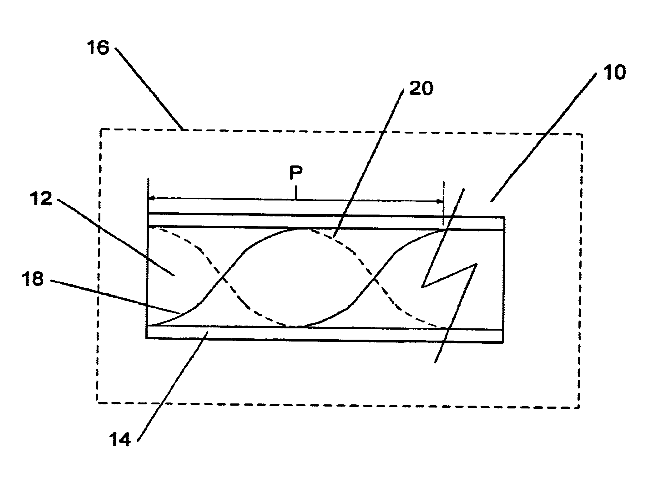
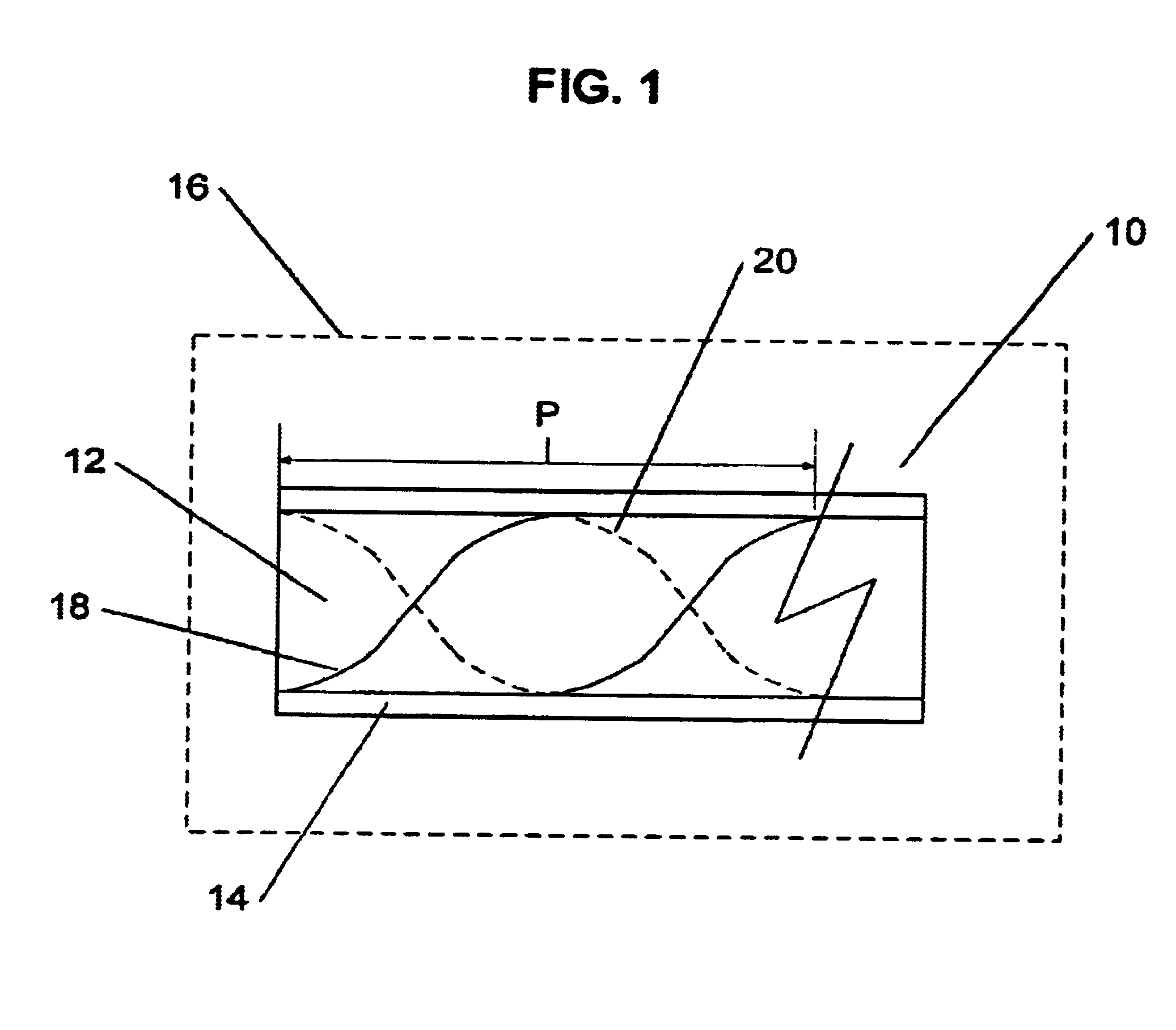
[0016]The present invention is directed to a novel optical chiral fiber having properties similar to a long period grating. The inventive long period chiral fiber grating is preferably fabricated by imposing (via twisting, wrapping and / or machining the fiber) one or two identical coaxial helices along the fiber's length. Preferably, the pitch of the inventive chiral fiber structure is of sufficient magnitude to impose long period grating properties thereon. It should be noted, that for the purposes of the present invention, a long period chiral fiber grating is defined as a fiber grating having a pitch that exceeds the wavelength of light propagating therethrough.

[0017]Referring now to FIG. 1, an exemplary embodiment of a long period chiral fiber grating 10 (hereinafter “LPCFG 10”) is shown. The LPCFG 10 includes a fiber core 12, and a cladding 14 surrounding the core 12. The coaxial helices 18 and 20 are formed by twisting a fiber having non-circular 180 degree cross sectional symm...


PUM


Abstract

A long period chiral fiber grating (“LPCFG”) that has a number of advantageous properties that can be readily utilized in a number of different applications is provided. The inventive LPCFG is a fiber grating having a pitch that exceeds the wavelength of light propagating therethrough. The LPCFG includes a number of dips in its transmission spectrum, but does not reflect any portion of the signal passing therethrough. The LPCFG is sensitive to changes in the refractive index of its external environment (or in the refractive index of a coating covering the LPCFG cladding). In response to changes in the external refractive index, the transmission dips shift proportionally to changes in the index, thus enabling the use of LPCFG as a fiber sensor element. In addition, the LPCFG is polarization sensitive—one circular polarized wave of one handedness is coupled to the cladding mode stronger than the wave of the other polarization handedness. This enables the LPCFG to be readily utilized in polarizers and for shaping the polarization spectra of signals passing therethrough (in one embodiment configured as multiple LPCFG elements having different pitches). The polarization sensitivity of the inventive LPCFG can also be used for verifying system integrity in chiral fiber sensor systems. In other embodiments of the present invention, the novel LPCFG can be used for modulating amplitude of the light signal propagating therethrough, or as a resonant active structure for add/drop filters.

Description

CROSS REFERENCE TO RELATED APPLICATIONS[0001]The present patent application claims priority from the commonly assigned U.S. provisional patent application Ser. No. 60 / 366,723 entitled “Long Period Chiral Fiber Grating” filed Mar. 22, 2002.FIELD OF THE INVENTION[0002]The present invention relates generally to fiber gratings, and more particularly to an optical fiber grating having long period grating properties.BACKGROUND OF THE INVENTION[0003]Fiber gratings are incorporated into components that form the backbone of modern information and communications technologies, and are suitable for a wide range of applications, such as information processing and optical fiber communication systems utilizing wavelength division multiplexing (WDM). There are many different fiber grating types and configurations. For example, fiber Bragg gratings are actually one-dimensional photonic stop band structures that are useful in lasing, filtering and sensing applications. Various Bragg grating configura...

Claims


Application Information

Patent Timeline
IPC IPC(8): G02B6/02G02B6/34G01L1/24G01K11/12G02B5/18G02B6/00
CPCG02B6/02085G02B6/02095G02B2006/0209
Inventor KOPP, VICTOR IL'ICHTCHOURIKOV, VICTOR
Owner CHIRAL PHOTONICS
Why Eureka
Try Eureka