Mixed-signal core design for concurrent testing of mixed-signal, analog, and digital components

a mixed-signal core and core design technology, applied in the field of methods, can solve the problems of entailing a substantial amount of complexity in testing next-generation socs, and reducing the overall test time, so as to reduce the overall test tim

Active Publication Date: 2005-08-02
TEXAS INSTR INC
View PDF8 Cites 17 Cited by
  • Summary
  • Abstract
  • Description
  • Claims
  • Application Information

AI Technical Summary

Benefits of technology

[0010]To address the above-discussed deficiencies of mixed-signal core design for testing, the present invention teaches a mixed-signal core designed for efficient testing capable of concurrent testing of the analog, mixed-signal, and digital components comprised within the mixed-signal core. A mixed-signal core in accordance with the present invention is enabled to use the same tester to test all components comprised within the core and, thereby, reduce test time without losing full test coverage.
[0014]Advantages of this design include but are not limited to a structure for testing a mixed-signal core on an SoC IC at a reduced test time over conventional mixed signal cores. This method and structure required for partitioning the logic design of the mixed-signal core and providing test support in accordance with the present invention helps reduce the overall test time for the SoC, while providing thorough test coverage. The mixed-signal core having partitioned modules that can be tested in parallel on the same chip, thereby reducing the overall test time.
[0015]The proposed technique not only assists in testing under normal conditions, but also during burn-in, wherein the analog module is dynamically burned using loop-back tests in the mixed-signal core for additional coverage and the digital modules is burned using scan and memory BIST patterns. This is in contrast to the traditional method where the analog module is powered down while the digital module is burned-in.
[0016]This partitioning scheme also helps in isolating and debugging the noise coupling issues between the analog and digital blocks. The test program can also be independently developed for the different partitions, and integrated later; thereby reducing the test development time.

Problems solved by technology

Designing such mixed-signal systems-on-chip (SoC) is distinctively challenging since it entails managing system level abstractions while simultaneously dealing with physical effects at the transistor and parasitic levels.
In addition, testing next-generation SoCs entails a substantial amount of complexity due to the cost and time-to-market requirements.
In general, testing of embedded analog / mixed-signal cores is considered a difficult problem in SoC IC testing.
Testing such a device is a challenge regarding coverage as well as expense; where coverage implies the amount of silicon which must be tested before it is shipped to customers.
Test cost directly stems from the amount of time to perform all testing.
Thus, for sequential testing of analog and digital modules incorporated within the SoCs using an ATE, the test time and expense may be double in a worst case scenario.
During these tests, the device is configured into scan test mode where device functionality is lost.
The disadvantage of this approach is that a large amount of test time is required to test the entire SoC device since it is difficult to test various blocks having different test methodologies in parallel.

Method used


Image

  • Mixed-signal core design for concurrent testing of mixed-signal, analog, and digital components
  • Mixed-signal core design for concurrent testing of mixed-signal, analog, and digital components
  • Mixed-signal core design for concurrent testing of mixed-signal, analog, and digital components

Examples


Embodiment Construction

[0027]The present invention will now be described more fully hereinafter with reference to the accompanying drawings, in which embodiments of the invention are shown. This invention may, however, be embodied in many different forms and should not be construed as limited to the embodiments set for the herein. Rather, these embodiments are provided so that this disclosure will be thorough and complete, and will fully convey the scope of the invention to those skilled in the art.

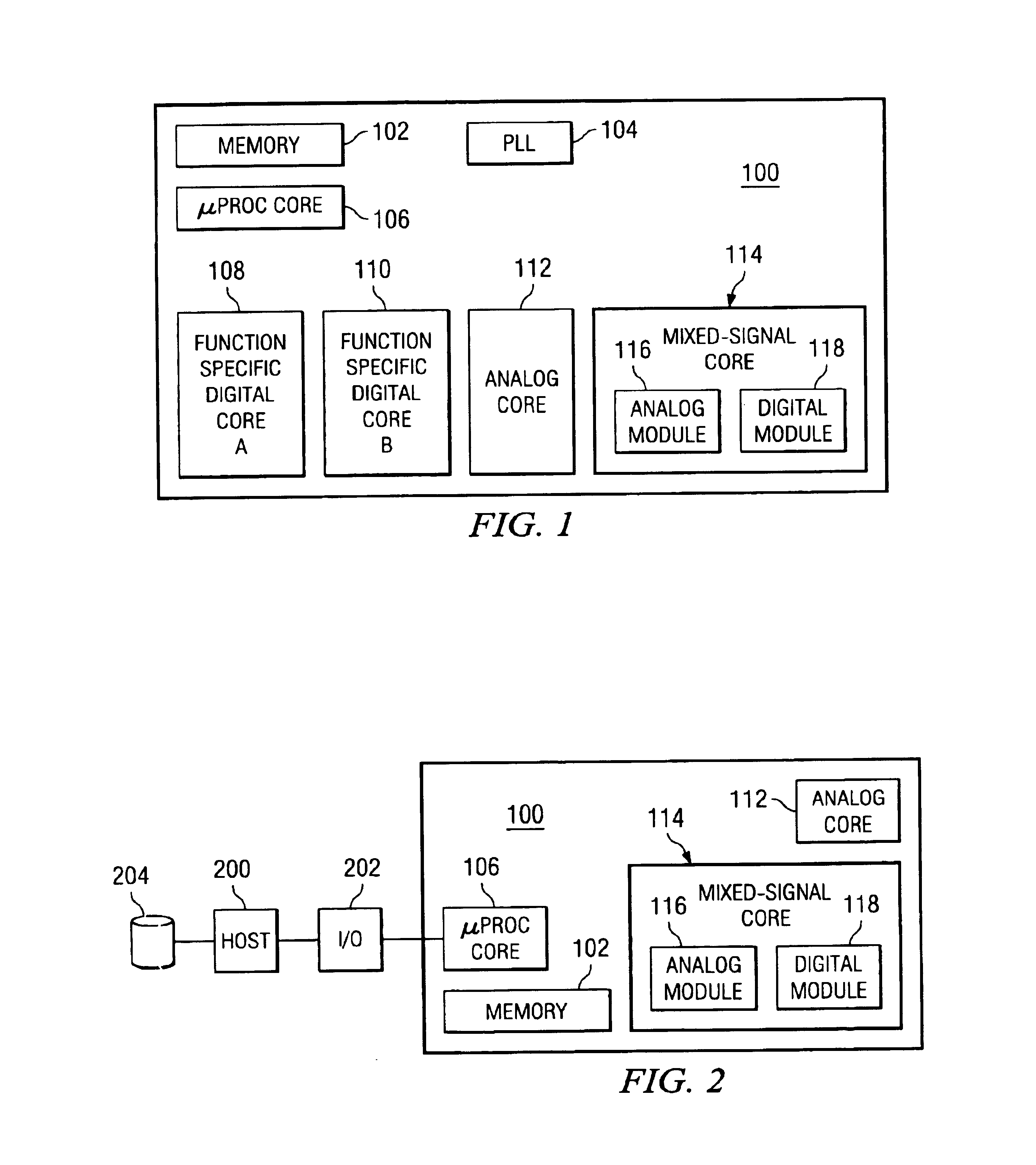
[0028]The present invention is best understood by comparison with the prior art. Hence, this detailed description begins with a discussion of known SoC IC similar to that shown in FIG. 1 as disclosed in U.S. Pat. No. 6,408,412 entitled “Method and Structure For Testing Embedded Analog / Mixed-Signal Cores In System-On-A-Chip”. FIG. 1 is a schematic diagram showing an example of the inner structure of such an SoC 100 that includes a memory core 102, a phase lock loop (PLL) 104, microprocessor core 106, function sp...


PUM


Abstract

A mixed-signal core designed for efficient concurrent testing analog, mixed-signal, and digital components. One tester may test all components and, thereby, reduce test time without losing full test coverage. An analog module includes all the analog and mixed-signal components of the mixed-signal core, while a first digital module includes digital components required for functional / parametric verification of the mixed-signal components within the analog module. A first virtual boundary connects the analog and the first digital modules to gate the signal transfer during testing. A second digital module includes the remaining digital components of the mixed-signal core, whereby a second virtual boundary separates it from the first digital module. This type of partitioning enables the mixed-signal core to have three modes of operation, using which the analog, mixed-signal and digital components can all be tested.

Description

[0001]This application claims priority under 35 USC § 119(e) (1) of provisional application Ser. No. 60 / 501,071, filed Sep. 8, 2003.FIELD OF THE INVENTION[0002]The present invention relates to a method and structure for testing an embedded mixed signal core on a System-on-Chip (SoC) design, and, more particularly, to a method and apparatus for partitioning and testing the embedded mixed signal core on the SoC integrated circuit (IC).BACKGROUND OF THE INVENTION[0003]In the advent of increased demand for consumer electronics and continued growth in semiconductor packing density, more system functionality is integrated onto an integrated circuit. Accordingly, there is an increased need for integration of analog and mixed-mode components (i.e. analog-digital, RF-analog-digital, and mechanical-analog-digital) on the same chip as digital components. Designing such mixed-signal systems-on-chip (SoC) is distinctively challenging since it entails managing system level abstractions while simu...

Claims


Application Information

Patent Timeline
Patent Type & Authority Patents(United States)
IPC IPC(8): G01R27/00G01R27/28G01R31/00G01R31/14G01R31/12G06F19/00G01R31/3167G01R31/317G01R31/3185G06J1/00
CPCG01R31/3167G01R31/31704G06J1/00G01R31/3172G01R31/318533
Inventor PREMY, AMITSURESH GUPTA, VUDUTHA V. N.AGASHE, ANUPAMA ANIRUDDHAKRISHNAMOORTHY, NIKILAPAREKHJI, RUBIN A.
Owner TEXAS INSTR INC
Why Eureka
Try Eureka