Method and device for treating contaminated materials

Inactive Publication Date: 2005-08-09
LOGTECH PATENT
View PDF11 Cites 8 Cited by
  • Summary
  • Abstract
  • Description
  • Claims
  • Application Information

AI Technical Summary

Benefits of technology

[0021]The conveyor system preferably has a screw conveyor. This can be designed to be reversible in order, if necessary, to reduce pressure if a transport bottleneck occurs. It is advantageous if the screw conveyor only has a bearing on one end and rests on slide runners.
[0022]It is very practical if a shredder is positioned in the input unit, which is particularly advantageous for the shredding of contaminated hospital

Problems solved by technology

In this known plant, it is disadvantageous that the two screw sections are separated by a mechanical pressure lock which is expensive and, of course, also represents a potential source of defects.
In addition, the screw sections are positioned in the horizontal plane in such a way that contaminated liquids can flow unnoticed through the plant and pass through the disinfection process untreated and/or insufficiently treated.
It is in no way assured here that a safe disinfection an

Method used


Image

  • Method and device for treating contaminated materials
  • Method and device for treating contaminated materials
  • Method and device for treating contaminated materials

Examples


Embodiment Construction

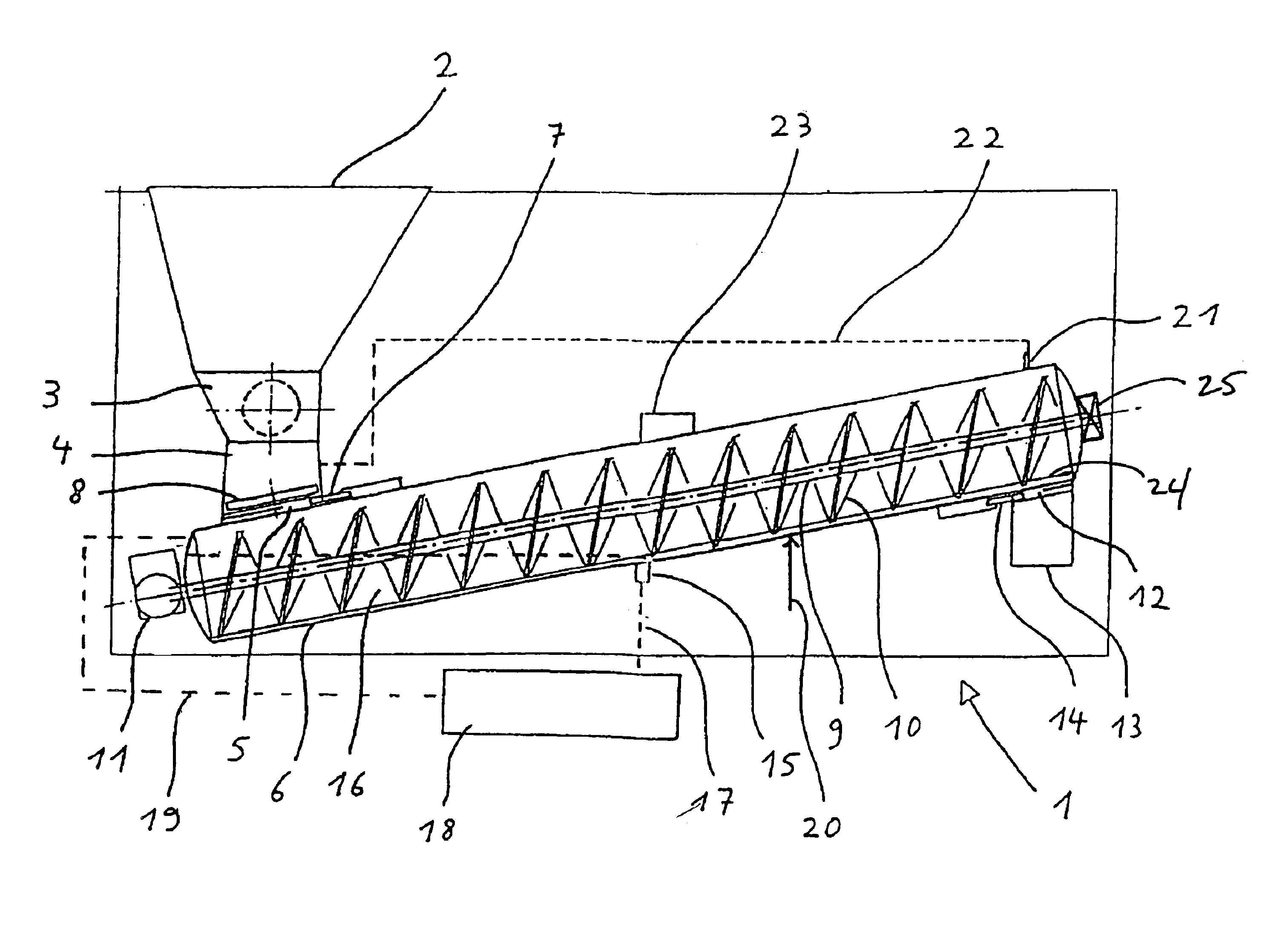
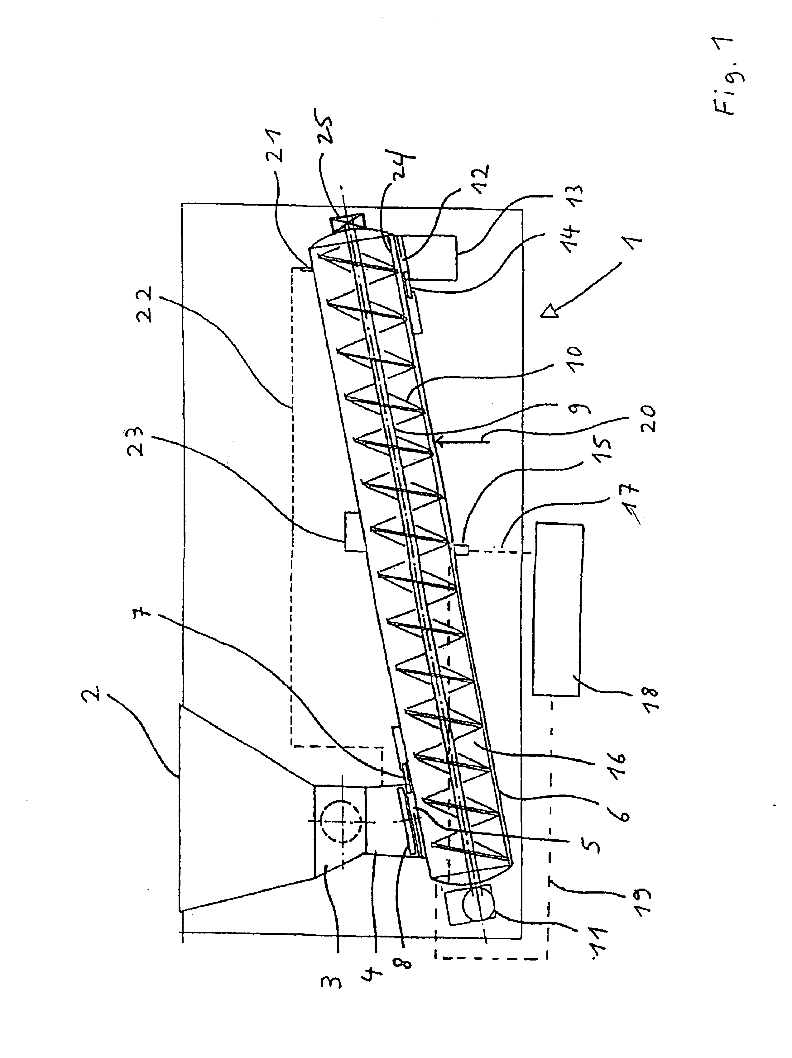
[0027]In FIG. 1, a device for the treatment of contaminated materials, particularly infected materials, is indicated with 1. The device 1 has a feed hopper 2, under which a shredder 3 is positioned, as a component of an input unit. From the shredder 3, a gravity feed hopper 4 leads to an intake 5 of a tube-shaped treatment chamber 6. The intake 5 can be closed by a slide valve 7. In place of the slide valve 7, or in addition to same, a lock could also be provided. A metering device 8 is position above the intake 5.

[0028]A screw conveyor 9 having a conveyor spiral 10 extends into the treatment chamber 6. The screw conveyor 9 is driven by a drive 11 has a bearing 25 at one end, and rests on slide runners 24. The treatment chamber 6 is slanted upwards in the transport direction of the screw conveyor 9, with, for example, an angle to the horizontal of approximately 10° to 40°. The screw conveyor 9 can rest on slide runners 24. A bearing 25 is provided at only one end of screw conveyor 9...


PUM

PropertyMeasurementUnit
Temperatureaaaaaaaaaa
Pressureaaaaaaaaaa
Areaaaaaaaaaaa

Abstract

A method and apparatus (1) for treating contaminated materials in which the materials are fed by an input unit (2, 3, 4) to a conveyor system (9) extending through a treatment chamber (6) where they are heated, treated and discharged via a discharge element (12). A liquid reservoir (16) is created in a first treatment area of the treatment chamber (6) by inclining the treatment chamber. The first area is also heated to a temperature below the boiling point of water, and a second area extending from th first treatment area to the top end of the treatment chamber (6) is at least partially heated to a temperature above the boiling point of water. This enables the contaminated material to be treated and compacted in a simpler, more reliable manner and in a (quasi-) continuous flow through several treatment areas.

Description

BACKGROUND OF THE INVENTION[0001]The invention concerns a method for the treatment of contaminated materials, particularly infected materials, whereby said materials are fed by means of an input unit to a conveyor system extending into a treatment chamber, where they are heated, treated, and discharged via a discharge element. Furthermore, the invention concerns a device for the above method in which essentially the entire treatment chamber is slanted upward in the direction of transport.[0002]A high-temperature disinfection plant for hospital-specific waste is already known from DE 39 38 546 C2 in which the wastes are supplied to two screw segments separated by a mechanical pressure-sealed intermediate lock via a receiving hopper. An adjustable steam pressure is hereby generated in the first screw segment through the introduction of heat, while a partial vacuum is generated in the second screw segment in order to dehumidify the material by sucking away the steam. In this known plan...

Claims


Application Information

Patent Timeline
IPC IPC(8): A61L11/00A61G12/00A61L2/06A61L2/12
CPCA61L11/00
Inventor GOELDNER, HELMUT
Owner LOGTECH PATENT
Why Eureka
Try Eureka