Method of providing an electroluminescent coating system for a vehicle and an electroluminescent coating system thereof

a technology of electroluminescent coating and vehicle, which is applied in the direction of liquid/solution decomposition chemical coating, electric lighting sources, vehicle seats, etc., can solve the problem that the initiation of luminescence resulting from the conventional phosphors cannot be effectively controlled, and the above compositions and the coating systems formed from these compositions are inadequate. to achieve the effect of effective control of electroluminescen

Inactive Publication Date: 2005-08-09
BASF CORP
View PDF12 Cites 26 Cited by
  • Summary
  • Abstract
  • Description
  • Claims
  • Application Information

AI Technical Summary

Problems solved by technology

On the other hand, EL phosphors have not been incorporated into coating systems for vehicles.
All of the above compositions and the coating systems formed from these coating compositions are inadequate.
In particular, the initiation of luminescence resulting from the conventional phosphors cannot be effectively controlled.
In other words, an operator cannot selectively activate the coating system to luminesce whenever the operator desires.
Furthermore, because these coating systems do not make use of the electricity of the vehicle, the duration of the luminescence cannot be effectively controlled.

Method used


Image

  • Method of providing an electroluminescent coating system for a vehicle and an electroluminescent coating system thereof
  • Method of providing an electroluminescent coating system for a vehicle and an electroluminescent coating system thereof
  • Method of providing an electroluminescent coating system for a vehicle and an electroluminescent coating system thereof

Examples


examples

[0044]The coating compositions were prepared by adding and reacting the following parts, by weight.

[0045]

AmountCoating CompositionComponent(grams)EL Coating CompositionBC 10029.9EL Phosphor15.0BC19055.1Total100.0Insulating Coating CompositionBC10085.9Dielectric Additive14.1Total100.0Conductive Coating CompositionBC 10050.0Electroconductive Additive50.0Total100.0

[0046]The BC100 component is thermoplastic and is a clear blend of a polyester resin and of CAB. The BC100 component is commercially available from BASF Corporation, Southfield, Mich.

[0047]The EL Phosphor component is a copper-doped zinc sulfide EL phosphor that has natural, i.e., off-white, electroluminescence, and that is commercially available as Phosphorescent Pigment 6SSU from United Mineral & Chemical.

[0048]The BC190 component is BC100 including titanium dioxide pigment and is commercially available from BASF Corporation, Southfield, Mich.

[0049]The Dielectric Additive component is barium titanate, BaTiO3, commercially a...


PUM

PropertyMeasurementUnit
dielectric constantaaaaaaaaaa
particle sizeaaaaaaaaaa
AC voltageaaaaaaaaaa

Abstract

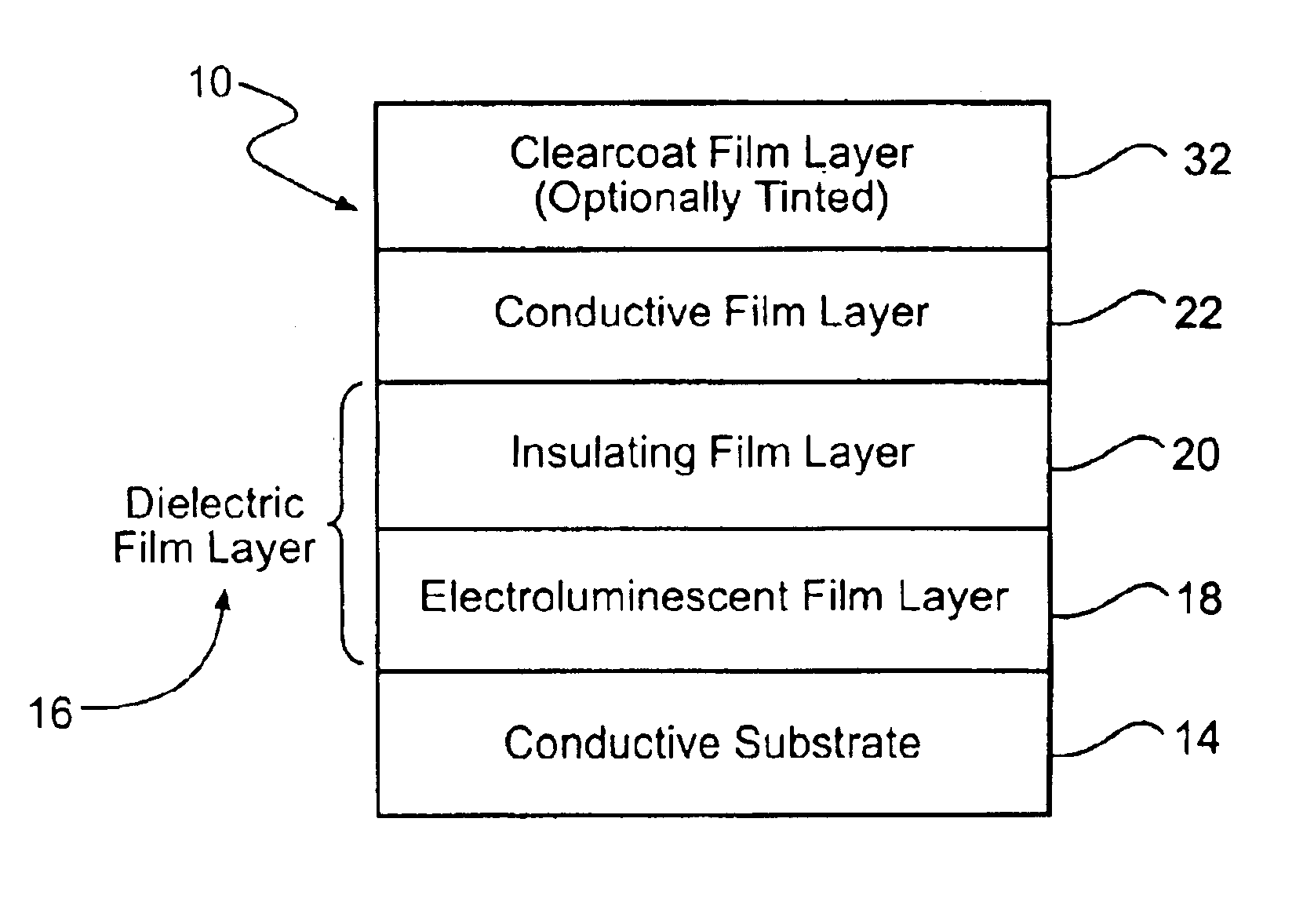
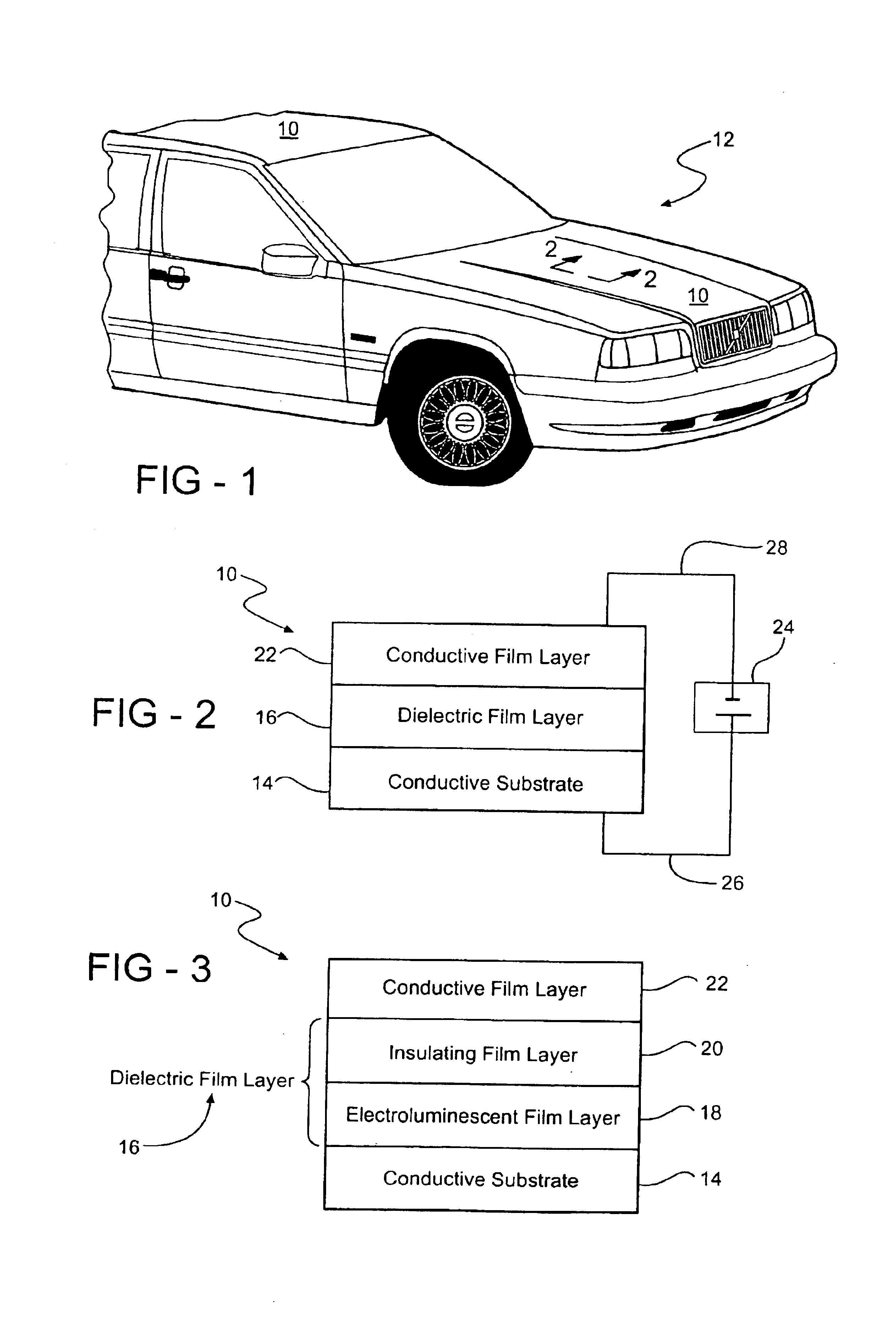
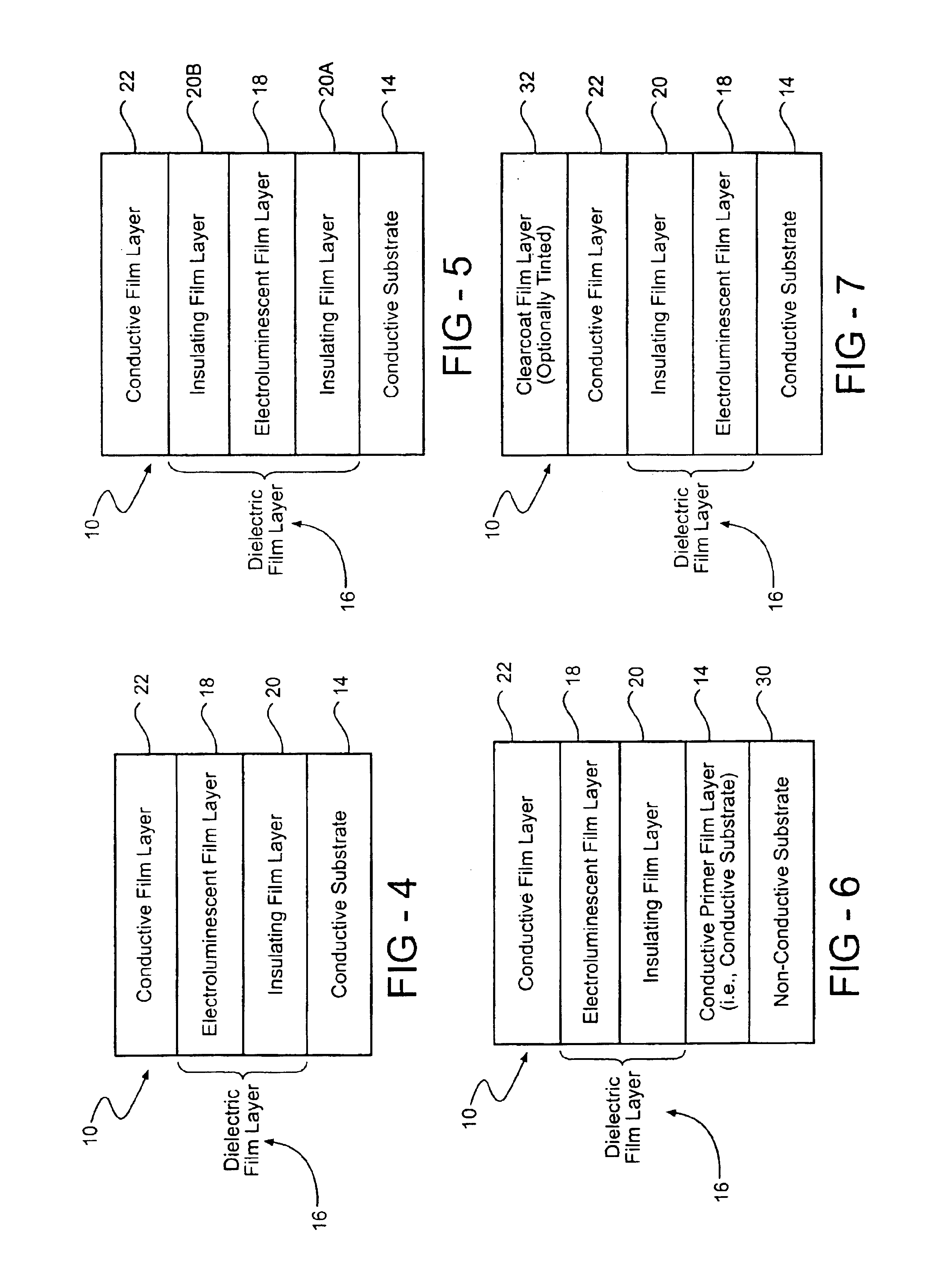
An electroluminescent (EL) coating system for a vehicle and a method of providing the EL coating system are disclosed. A dielectric coating composition is applied to a conductive substrate, such as an automotive body panel. Application of the dielectric coating composition, which includes an EL phosphor, forms a dielectric film layer on the substrate. A conductive coating composition, which includes an electroconductive additive, is applied to the dielectric film layer to form a conductive film layer on the dielectric film layer. The dielectric coating composition is disposed between the substrate and conductive film layer such that the conductive film layer remains spaced from the substrate. The EL phosphor in the dielectric film layer is excitable by an electrical field established across the dielectric film layer. As such, the coating system of the vehicle is EL, or ‘electroluminesces,’ upon application of an electrical charge to the substrate and the conductive film layer.

Description

FIELD OF THE INVENTION[0001]The subject invention generally relates to an electroluminescent (EL) coating system for a vehicle and a method of providing the EL coating system. More specifically, the EL coating system of the subject invention includes a conductive substrate, such as an automotive body panel of the vehicle, a dielectric film layer having an EL phosphor, and a conductive film layer.BACKGROUND OF THE INVENTION[0002]EL phosphors are known and are used throughout various industries. EL phosphors exhibit electroluminescence in response to application of an alternating current voltage to the EL phosphor. EL phosphors may also exhibit electroluminescence in response to an electrical field generated by the alternative current voltage. As a result, EL phosphors are used, for example, in personal digital assistant (PDA) displays, cellular phone displays, in watches, and even in luminescent lighting technology.[0003]It is also known to use conventional phosphors in coating compo...

Claims


Application Information

Patent Timeline
Patent Type & Authority Patents(United States)
IPC IPC(8): C09D5/22G09F13/22H05B33/10H05B33/12
CPCC09D5/22G09F13/22H05B33/10H05B33/12G09F2013/227Y10S428/917Y10T428/31554Y10T428/31605Y10T428/31681
Inventor JAKOBI, MICHAELSERDIUK, PAUL
Owner BASF CORP
Why Eureka
Try Eureka