High voltage supply circuit and a method of supplying high voltage

a high-voltage supply and high-voltage technology, applied in the direction of electric variable regulation, process and machine control, instruments, etc., can solve the problems of data loss, high possibility, and low pumping voltage (vpp) above the target voltage, and achieve the effect of increasing the reliability of the circui

Inactive Publication Date: 2005-08-16
MOSAID TECH
View PDF6 Cites 15 Cited by
  • Summary
  • Abstract
  • Description
  • Claims
  • Application Information

AI Technical Summary

Benefits of technology

[0010]The present invention is contrived to solve the aforementioned problems. An object of the present invention is to provide a high voltage supply circuit and method of supplying a high voltage, which can prevent a pumping voltage from being lower than a target voltage even if the circuit enters an operating mode where current consumption is abruptly increased, and stably operate the circuit to increase reliability of the circuit, in such a manner that an assistant pumping voltage-generating unit other than a pumping voltage-generating unit for generating the pumping voltage is further provided, and the assistant pumping voltage-generating unit is operated for a certain time simultaneously when a normal operating mode is switched to the operating mode where current consumption is abruptly increased, thus raising the pumping voltage higher than the target voltage.

Problems solved by technology

For this reason, there is a high possibility that the data may be lost.
However, if the normal mode is switched to an operating mode where current consumption is abruptly increased such as the auto-refresh operation, there is a problem that the pumping voltage (Vpp) is lower than the target voltage and is then increased up to the target voltage.
The circuit may be thus erroneously operated in this period.
Accordingly, there is a problem that reliability in the operation of the circuit is degraded.

Method used


Image

  • High voltage supply circuit and a method of supplying high voltage
  • High voltage supply circuit and a method of supplying high voltage
  • High voltage supply circuit and a method of supplying high voltage

Examples


Embodiment Construction

[0023]The present invention will now be described in detail in connection with preferred embodiments with reference to the accompanying drawings.

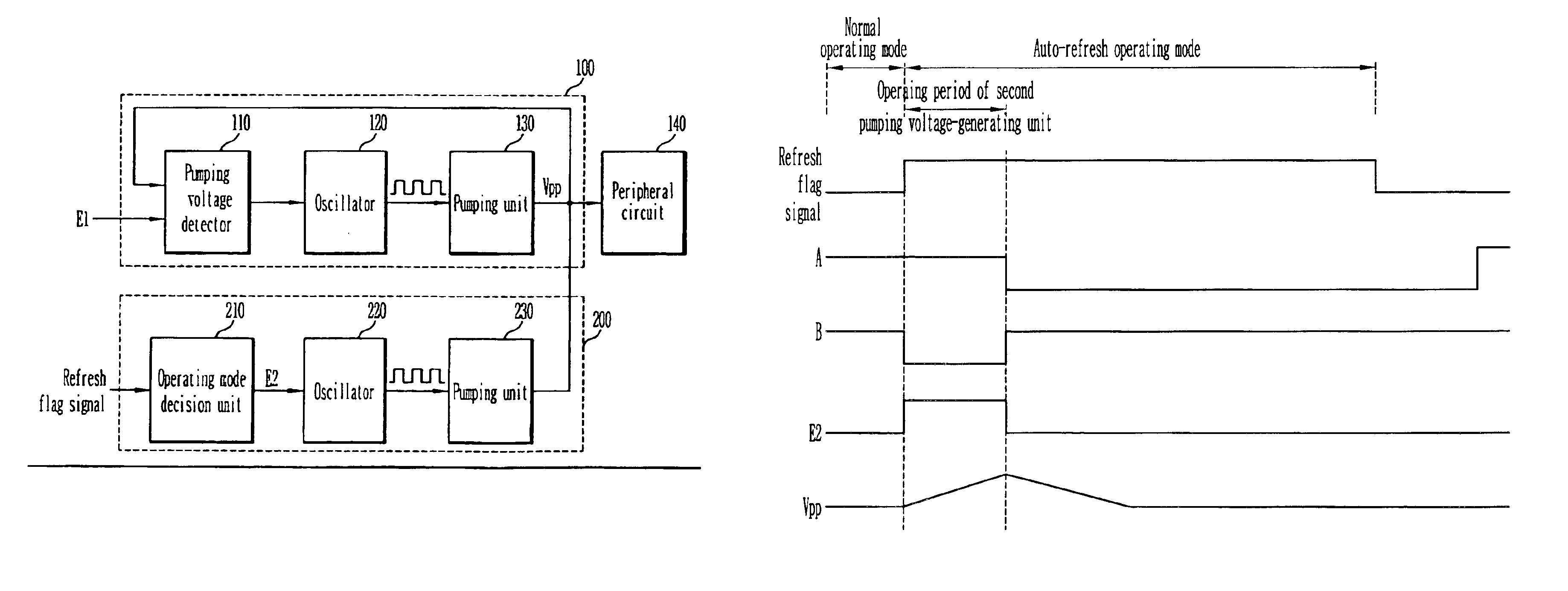
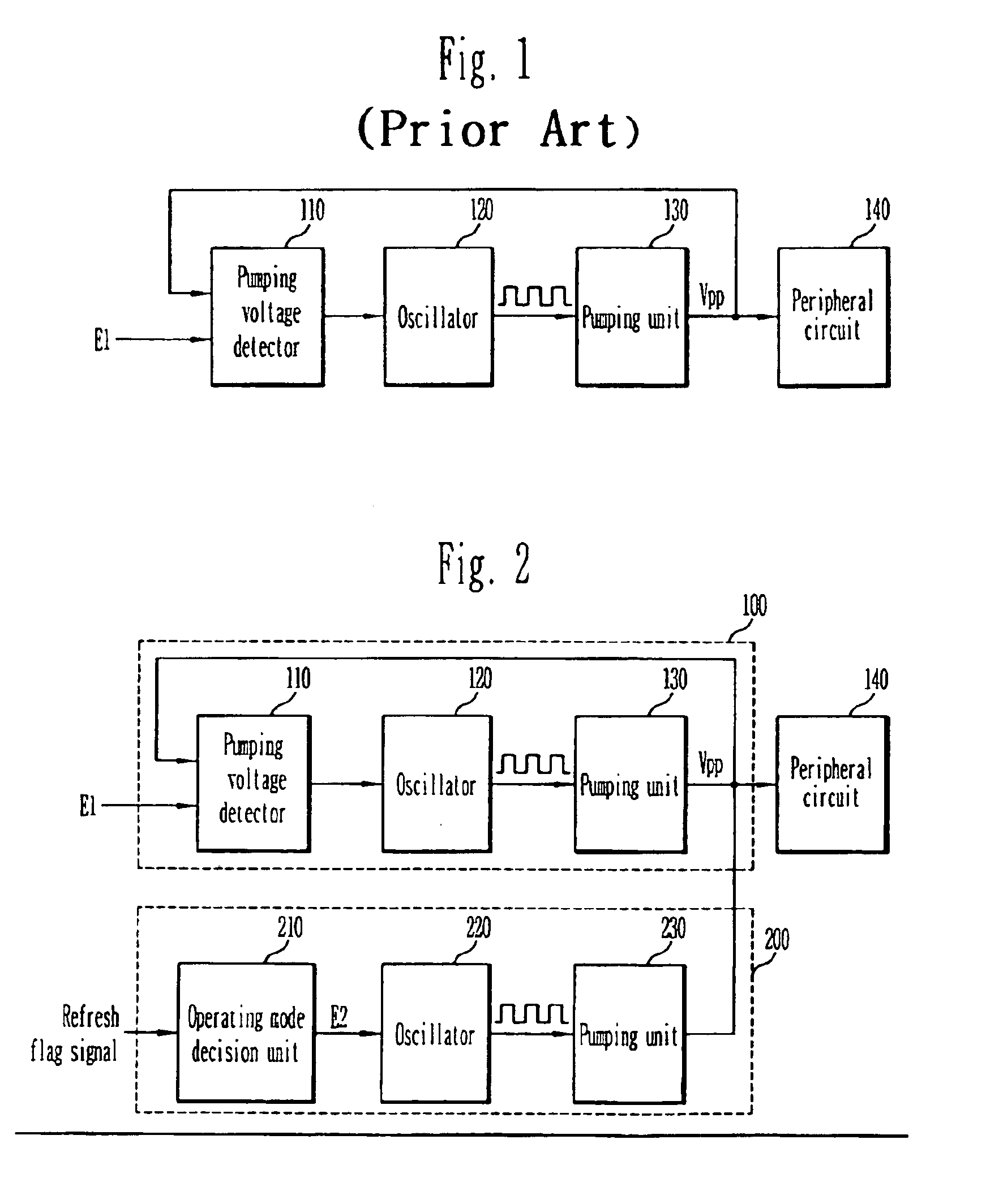
[0024]FIG. 2 is a block diagram illustrating a high voltage supply circuit according to one embodiment of the present invention.

[0025]Referring to FIG. 2, the high voltage supply circuit of the present invention includes a first pumping voltage-generating unit 100 and a second pumping voltage-generating unit 200. The first pumping voltage-generating unit 100 includes a pumping voltage detector 110, an oscillator 120 and a pumping unit 130.

[0026]If the entire circuit is initialized and then normally starts to operate, an active signal is generated. The active signal is applied to the pumping voltage detector 110 as an enable signal E1. Based on the enable signal, the pumping voltage detector 110 determines the potential of a pumping voltage (Vpp) generated in the pumping unit 130. The oscillator 120 generates a pulse signal according to the ...


PUM


Abstract

A high voltage supply circuit and method of supplying a high voltage are disclosed. A second pumping voltage-generating unit, in addition to a primary pumping voltage-generating unit for generating a pumping voltage, is provided. The second pumping voltage-generating unit is operated for a certain time simultaneously with the primary voltage-generating unit when a normal operating mode is switched to an auto-refresh operating mode where current consumption is abruptly increased in order to raise the pumping voltage higher than a target voltage. Therefore, the resulting pumping voltage is prevented from being lower than the target voltage even if the operating mode where current consumption is abruptly increased is entered, and the reliability of the circuit is therefore increased.

Description

BACKGROUND OF THE INVENTION[0001]The present invention relates to a high voltage supply circuit and method of supplying a high voltage, and more particularly, to a high voltage supply circuit and method of supplying a high voltage, capable of preventing a pumping voltage from being lowered than a target voltage.[0002]In general, a unit cell of a DRAM consists of one MOS type transistor serving as a switch and one capacitor for storing a charge (data). A plurality of the unit cells are classified into banks. At this time, the unit cell has a binary data stored therein. Depending on a charge state stored in the capacitor included in the unit cell, the data stored in the unit cell is divided into ‘1’ or ‘0’. As such, as the data is decided depending on the charge stored in the capacitor, there is no power consumption in principle.[0003]As the leakage current occurs in a PN junction of the MOS transistor, etc., however, the amount of the charge stored in the capacitor is gradually reduc...

Claims


Application Information

Patent Timeline
Patent Type & Authority Patents(United States)
IPC IPC(8): H02M3/07H02M3/04G11C11/407G11C5/14G11C11/403
CPCH02M3/073H02M2001/0032H02M2003/077Y02B70/16H02M1/0032H02M3/077Y02B70/10G11C5/14
Inventor KIM, KWAN WEON
Owner MOSAID TECH
Why Eureka
Try Eureka