Dual-element microstrip patch antenna for mitigating radio frequency interference

a patch antenna and microstrip technology, applied in the field of patch antennas, can solve problems such as disrupting their independent operation, and achieve the effect of less sensitivity and higher sensitivity

Inactive Publication Date: 2005-08-16
THE BOARD OF TRUSTEES OF THE LELAND STANFORD JUNIOR UNIV
View PDF10 Cites 62 Cited by
  • Summary
  • Abstract
  • Description
  • Claims
  • Application Information

AI Technical Summary

Benefits of technology

[0017]According to one aspect of the invention, an antenna has two patch antenna elements with similar azimuth radiation patterns but distinct elevation radiation patterns. The two antenna elements are in sufficiently close proximity to each other that strong mutual coupling would normally take place, disrupting their independent operation. Nevertheless, the two antenna elements may be operated independently of each other by selectively disabling one or the other of the two elements. More specifically, diodes are used to isolate the two element

Problems solved by technology

The two antenna elements are in sufficiently close proximity to each other that stro

Method used


Image

  • Dual-element microstrip patch antenna for mitigating radio frequency interference
  • Dual-element microstrip patch antenna for mitigating radio frequency interference
  • Dual-element microstrip patch antenna for mitigating radio frequency interference

Examples


Embodiment Construction

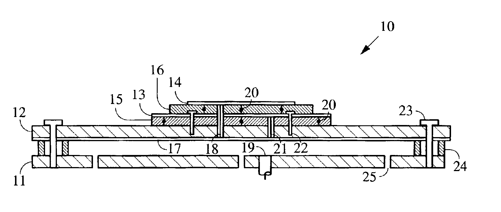
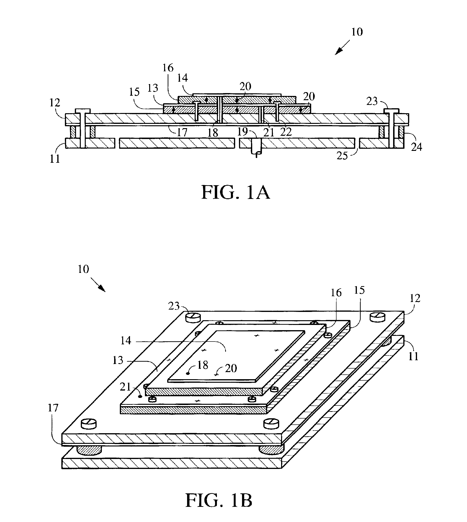
[0028]As shown in FIGS. 1A and 1B, an embodiment of the present invention provides a dual-element antenna device comprising two vertically stacked rectangular microstrip patch antenna elements 13 and 14, dielectric substrates 15 and 16, and a conducting ground plate 12. Antenna elements 13 and 14 are stacked above ground plate 12 with substrates 15 and 16 interposed between them. The two patch elements 13 and 14 are fed simultaneously by a common feed 18 located along a diagonal of the rectangular patch elements. The feed 18 is located from the corner of the rectangle of both patches approximately 35 percent of the length of the diagonal. In this configuration, both upper and lower patch elements will be circularly polarized. In addition, the patches are electrically in series with each other. The upper patch 14 operates in the nominal or general purpose mode. When active, the upper patch 14 and the lower patch 13 form a resonant cavity at the frequency of interest, using the upper ...


PUM


Abstract

Method and apparatus for reducing radio frequency interference (RFI) using a dual-element patch antenna [10]. The antenna possesses two antenna elements [13, 14] having distinct radiation patterns. Either element may be independently selected using a DC bias voltage. Diodes [20] connected to the elements serve to disable one element when the other is selected. In one selected mode, a nominal radiation pattern provides a broad, hemispherical shaped sensitivity that is designed for acquiring and tracking all navigation satellites above the horizon. This nominal radiation pattern, however, is susceptible to interference that is present near or below the horizon. The second selectable radiation pattern of the dual-element antenna has comparatively higher gain toward zenith, and lower gain at and below the horizon to mitigate interference. This combination of features is packaged in a single antenna unit that can be a direct replacement for existing antennas. The dual-element antenna unit has a low vertical profile and is suitable for mounting on high-speed moving vehicles.

Description

CROSS-REFERENCE TO RELATED APPLICATIONS[0001]This application claims priority from U.S. provisional patent application No. 60 / 364,496 filed Mar. 15, 2002, which is incorporated herein by reference.FIELD OF THE INVENTION[0002]This invention relates generally to radio frequency interference and particularly to patch antennas capable of significantly reducing and / or preventing radio frequency interference to satellite radio navigation systems.BACKGROUND OF THE INVENTION[0003]Satellite radio navigation systems such as the Global Positioning System (GPS) are valuable tools for the navigation of moving vehicles. These vehicles may be ground or air vehicles, and may be manned or unmanned. Traditionally, GPS antennas for moving vehicles have been microstrip patch antennas which have a low vertical profile and low wind resistance. These antennas are lightweight, inexpensive, and typically only several inches square, and may protrude one or two centimeters above the surface of the vehicle, at...

Claims


Application Information

Patent Timeline
IPC IPC(8): H01Q1/38H01Q9/04H01Q3/24H01Q21/28H01Q21/00
CPCH01Q1/38H01Q3/247H01Q9/0414H01Q9/0428H01Q9/0442H01Q21/28
Inventor BAUREGGER, FRANK N.ENGE, PERWALTER, TODDAKOS, DENNIS
Owner THE BOARD OF TRUSTEES OF THE LELAND STANFORD JUNIOR UNIV
Why Eureka
Try Eureka