
Q-switching method for pulse train generation

a pulse train and switching technology, applied in the direction of lasers, optical resonator shape and construction, manufacturing tools, etc., can solve the problems of insufficient compensation, resonator) or too slow, and significant change in laser spatial mod

Active Publication Date: 2005-08-16
COHERENT INC
View PDF26 Cites 20 Cited by
  • Summary
  • Abstract
  • Description
  • Claims
  • Application Information

AI Technical Summary

Benefits of technology

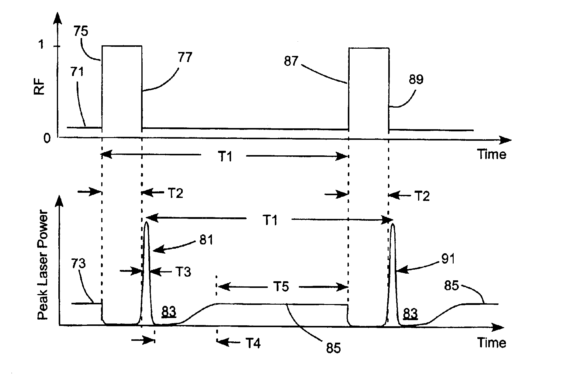
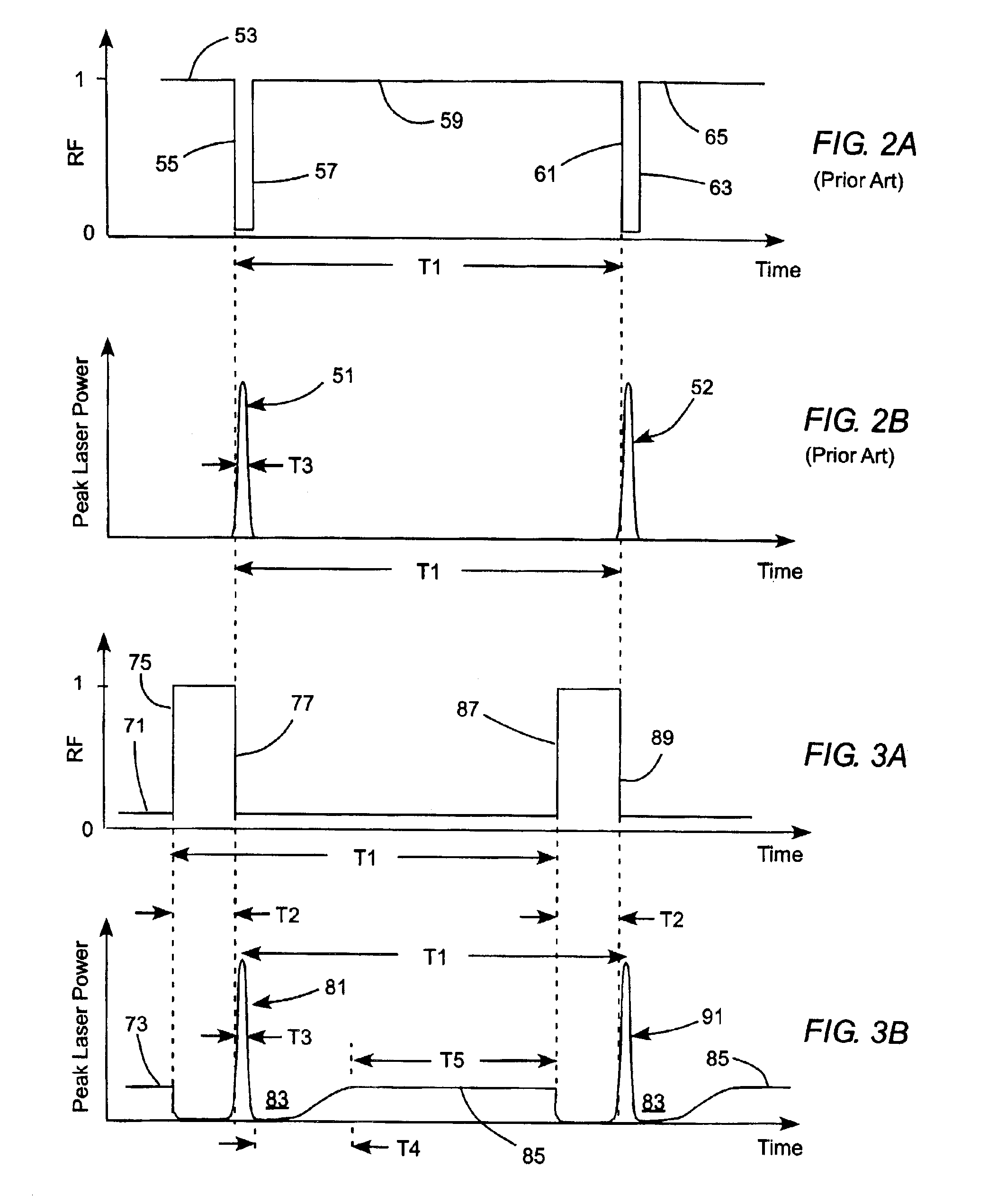
[0010]In another aspect of the present invention, the interruption period and the time period between sequential pulses are selected such that the average radiation power delivered in interrupted and uninterrupted CW operation is about the same. If the continuous pumping power is held constant, this causes thermal-lensing effects in the solid-state gain-medium to remain constant during and between deliveries of seq...

Problems solved by technology

Compensation can be insufficient (in the case of a fixed resonator) or too slow (in the case of a dynamically compensated resonator).
It can be seen that significant thermal lensing variation can occur and can result in significant change in laser spatial mode if the laser is switched between the two different PRFs.
This can result in a problem in providing precise machining or marking for example.
The problem is exacerbated if pulses of fundamental radiation from the resonator are frequency converted, for example, to generate second, third, or fourth harmonic wavelengths, in one or more optically-nonlinear crystals before being used in a particular application.
While the method is generally effective it is not always possible to eliminate thermal-lensing changes effectively in the transition to delivery of machining pulses from delivery of non-machining pulses (or CW laser beam).
Operation of the laser is further complicated by the fact that, even when it is possible to equate thermal lensing between and during machining-pulse delivery periods, it is necessary to allow a particular delay between the delivery of thermal-lensing-control pulses (or CW laser beam) and delivery of machining pulses.

Method used


Image

  • Q-switching method for pulse train generation
  • Q-switching method for pulse train generation
  • Q-switching method for pulse train generation

Examples


Embodiment Construction

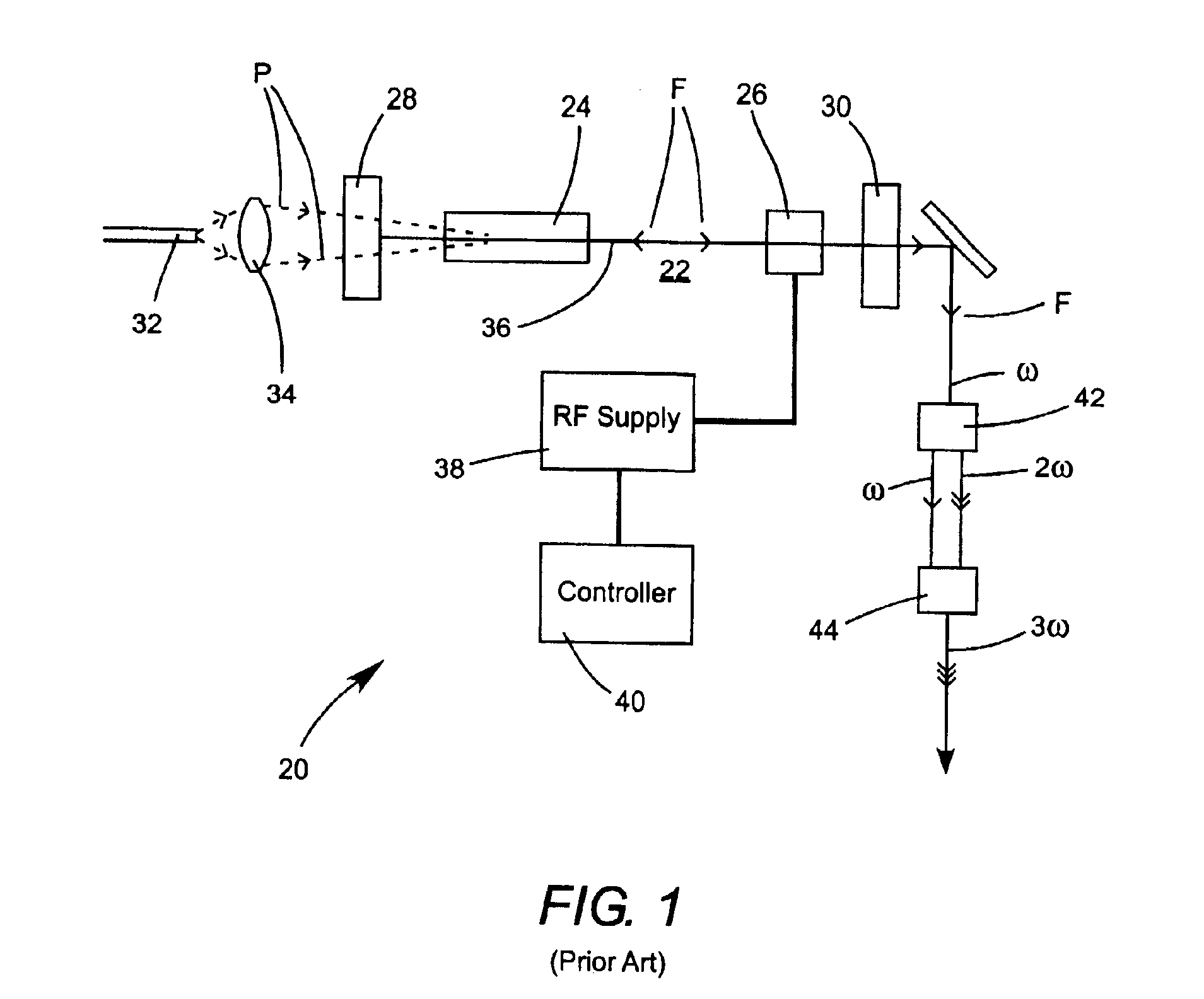
[0016]Referring now to the drawings, wherein like features are identified by like reference numerals, FIG. 1 schematically illustrates a basic, prior-art solid-state laser 20 having a laser resonator 22 including a solid-state gain-medium 24 and a Q-switch 26. Resonator 22 is formed between mirrors 28 and 30. Gain-medium 24 is continuously optically end-pumped by pump-light P delivered thereto via an optical fiber 32 and a lens 34 from a source such as a diode-laser or a diode-laser array. Fundamental laser radiation generated in the resonator in response to the optical pumping circulates along a longitudinal axis 36 of resonator 22, as indicated by single arrows F. Mirror 30 is made partially transmitting for the wavelength of the fundamental radiation to allow delivery of the radiation from the resonator.

[0017]If gain-medium 24 exhibits a significant thermal-lensing effect, resonator 22 is arranged to compensate for a range of such thermal lensing by selecting appropriate resonato...


PUM

PropertyMeasurementUnit
Poweraaaaaaaaaa
Nonlinear systemaaaaaaaaaa

Abstract

A method of operating a continuously pumped, Q-switched laser to provide trains of pulses for laser operations is disclosed. The laser includes a solid-state gain-medium that exhibits a thermal-lensing effect on being optically pumped. Pulse delivery is controlled by a Q-switch that is in a normally-open state when the laser is not delivering pulses. This allows the laser to deliver CW laser radiation when pulses are not being delivered. A train of pulses is delivered by repeatedly interrupting the CW operation by closing then reopening the Q-switch. When the Q-switch reopens after the interruption, the laser delivers a pulse of laser radiation, then resumes delivery of CW operation until the next interruption. The interruption periods may be varied to provide pulses of different peak power in a pulse train.

Description

TECHNICAL FIELD OF THE INVENTION[0001]The present invention relates generally to generating laser pulse trains in a continuously pumped, solid-state laser. The invention relates in particular to a method of generating a pulse train in a continuously pumped, solid-state laser by repeatedly interrupting CW operation of the laser using a Q-switch.DISCUSSION OF BACKGROUND ART[0002]Pulsed lasers are used widely in applications such as microvia drilling, materials marking, stereo lithography, and biosciences. In many of these applications, both precision and flexibility of operation are important. Precision requires that the laser have consistent and essentially identical beam propagation properties and the same laser pulse energy from pulse to pulse. Flexibility includes being able to provide complex pulse trains with variable time periods therebetween. The time period between pulses can range from a tens of microseconds (μs) to a second or greater.[0003]An optimum combination of precisi...

Claims


Application Information

Patent Timeline
IPC IPC(8): B23K26/06H01S3/11H01S3/127H01S3/08
CPCB23K26/06H01S3/117H01S3/08072H01S3/10038H01S3/1068B33Y30/00
Inventor WANG, CHARLES X.
Owner COHERENT INC
Learn More