
Peak limiter and multi-carrier amplification apparatus

a multi-carrier amplification and limiter technology, applied in the field of multi-carrier amplification apparatus, can solve the problems of low limit level of baseband input signal, nonlinear distortion of amplified signal, and ineffective peak limitation, and achieve the effect of enhancing power efficiency and effective peak limitation

Active Publication Date: 2005-08-16
KOKUSA ELECTRIC CO LTD
View PDF8 Cites 28 Cited by
  • Summary
  • Abstract
  • Description
  • Claims
  • Application Information

AI Technical Summary

Benefits of technology

[0031]It is, therefore, an object of the present invention to provide a peak limiter and a multi-carrier amplification apparatus capable of effectively performing peak limitation in order to precisely obtain a desired peak factor of an input signal of an amplifier to thereby enhance the power efficiency thereof.
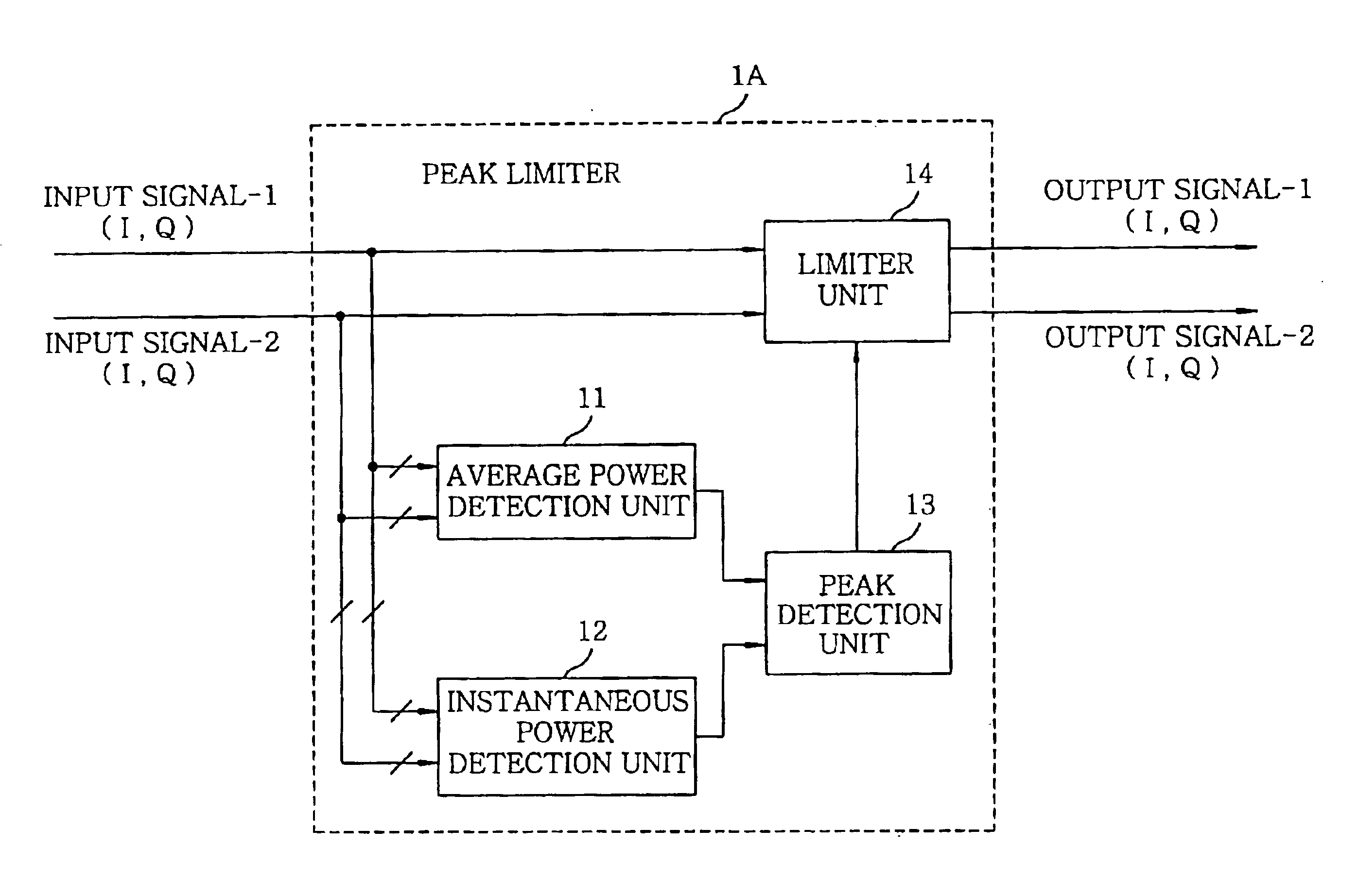
[0032]In accordance with a preferred embodiment of the present invention, there is provided a peak limiter for use in a system for amplifying a multi-carrier signal, wherein the peak limiter, responsive to baseband signals of carriers of the multi-carrier signal, computationally estimates the multi-carrier signal by combining the baseband signals in an RF band to obtain power information of the estimated multi-carrier signal, and limits an amplitude of each of the baseband signals based on the power information of the estimated multi-carrier signal to thereby provide peak-limited baseband signals.

Problems solved by technology

Such nonlinear output leads to a nonlinear distortion in the output signal.
However, after the transmission signal is amplified at the amplifier, the amplified signal exhibits a nonlinear distortion, entailing a leak of a part of the amplified signal into adjacent channels.
In other cases, however, the limit level of the baseband input signal is set to be low.
However, in the prior art peak limiter and multi-carrier amplification apparatus, the peak limitation is carried out with respect to the individual input signal based on a peak factor and a peak threshold value of each input signal; and the peak-limited signals are combined after band limitation.
Therefore, the peak threshold value is predetermined conservatively low for the sake of safety, so that effective peak limitation can not be performed.
Moreover, even in a case where an actual power of the multi-carrier signal coupled at the coupler 4 is small, the peak limitation is performed on individual input signal if instantaneous-to-average power ratios thereof are greater than the predetermined peak threshold value, resulting in unnecessary peak limitation, which in turn deteriorates the modulation accuracy.

Method used


Image

  • Peak limiter and multi-carrier amplification apparatus
  • Peak limiter and multi-carrier amplification apparatus
  • Peak limiter and multi-carrier amplification apparatus

Examples


Embodiment Construction

[0049]The inventive features of the present invention can be realized by any other circuits or apparatus than those described in the preferred embodiments of the invention as long as they can realize such features. Further, some or all of the functions thereof may be implemented by software. In addition, each of certain functional elements of the system can be implemented by a plurality of circuits or a multiplicity of such functional elements of the system can be configured in a single circuit.

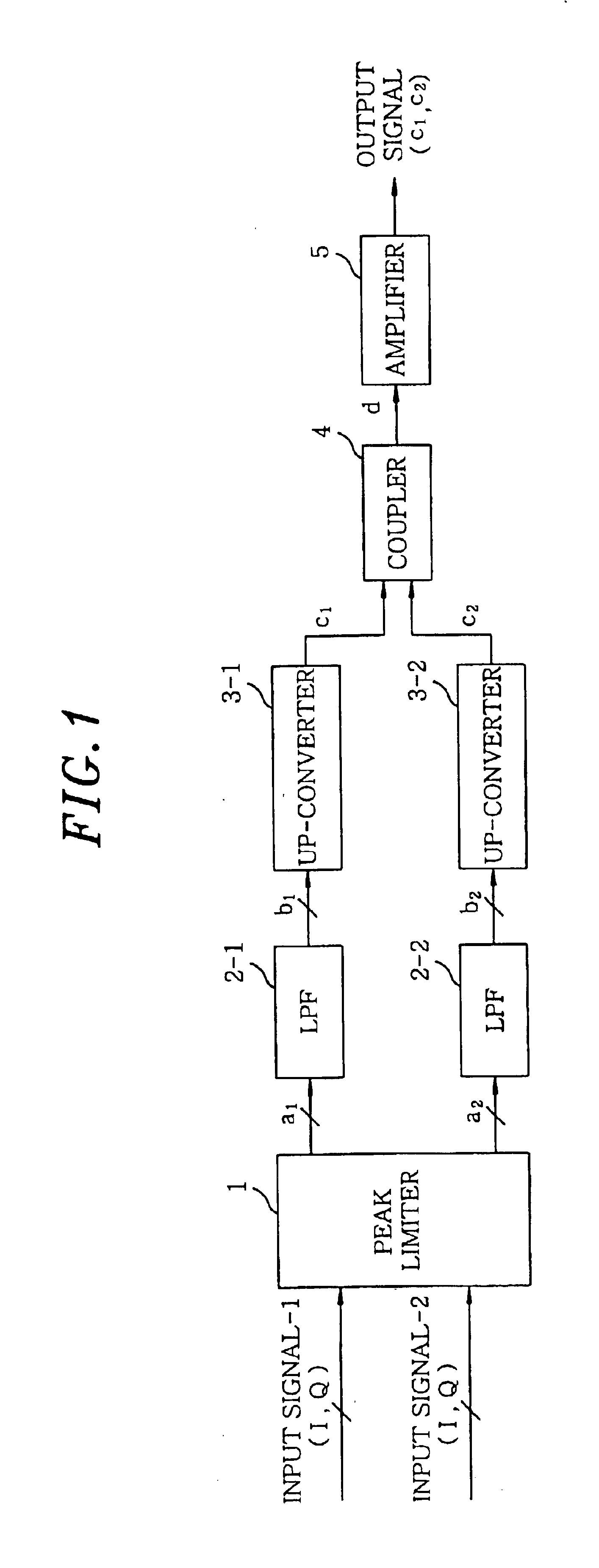
[0050]Referring to FIG. 1, there is illustrated a block diagram of a multi-carrier amplification apparatus in accordance with the present invention, wherein like reference numerals are used to represent like parts of the conventional multi-carrier amplification apparatus shown in FIG. 11.

[0051]The multi-carrier amplification apparatus in accordance with the present invention includes low-pass filters (LPF) 2-1 and 2-2 for filtering respective peak-limited signals a1 and a2 (two input signals ...


PUM


Abstract

A peak limiter for use in a system for amplifying a multi-carrier signal receives a baseband signal of each carrier of the multi-carrier signal. The multi-carrier signal is computationally estimated to have carriers combined in an RF band, and obtains power information of the multi-carrier signal to limit an amplitude of the baseband signal based on the power information of the estimated multi-carrier signal to thereby provide peak-limited baseband signals. Thus, the distortion generated by performing the unnecessary peak limitation can be effectively prevented to thereby improve the reliability of the entire system.

Description

FIELD OF THE INVENTION[0001]The present invention relates to a peak limiter and a multi-carrier amplification apparatus for use in a system for amplifying a multi-carrier signal, e.g., a base station of a mobile communications system employing a W-CDMA technique; and, more particularly, to a peak limiter and a multi-carrier amplification apparatus capable of enhancing power efficiency of the amplification system.BACKGROUND OF THE INVENTION[0002]In general, a relatively high transmission power level is required for proper communications between a remote mobile station and a base station of a mobile communications system employing, e.g., W-CDMA (Wideband Code Division Multiple Access) scheme. In such a case, communication signals sometimes need be highly amplified at a transmission end, e.g., the base station.[0003]An amplifier, which is an analog device, generally exhibits nonlinear input / output characteristics. Specifically, the output power of the amplifier becomes almost constant ...

Claims


Application Information

Patent Timeline
IPC IPC(8): H03G11/00H03G11/04H04L27/26
CPCH03G11/04H04L27/2623
Inventor HONGO, NAOKIOKUBO, YOICHISUTO, MASAKIHORAGUCHI, MASATOTAKADA, TOSHIOMIYATANI, TETSUHIKO
Owner KOKUSA ELECTRIC CO LTD
Learn More