
Rebound attenuation device for automatic firearms

a technology of automatic firearms and attenuation devices, which is applied in the direction of gun mountings, muzzle attachments, weapons, etc., can solve the problems of increased striking power and range of standard ammunition, unexpected dangers from the increase of standard ammunition, and modification of weapons that can become prohibitively expensive, so as to reduce the tendency for “bounce” and the effect of sufficient tim

Active Publication Date: 2005-08-23
GENERAL DYNAMICS ORDNANCE & TACTICAL SYST CANADA VALLEYFIELD INC
View PDF4 Cites 58 Cited by
  • Summary
  • Abstract
  • Description
  • Claims
  • Application Information

AI Technical Summary

Benefits of technology

[0011]According to one aspect of the invention, a unitary bolt carrier assembly with a bolt is provided for an automatic firearm operating in blow-back mode wherein the bolt carrier assembly is slideably mounted in the receiver for shifting between a first position wherein the bolt is in-battery against at the breech and a second position wherein the bolt in its bolt carrier assembly is removed from the breech while cycling. A weight means is provided which is slideably mounted to move in a containment space that travels with the bolt carrier assembly while the weapon is cycling in blow-back mode. When the weapon is cycling with the bolt carrier assembly having moved rearwardly away from the breach to the limit of its travel, the weight means will slide in its containment space in a direction away from the breech to the limit permissible and then so remain at that location on the return stroke until the bolt is again at the in-battery position. When the bolt carrier assembly has returned to the in-battery position the weight means will slide forwardly in its containment space towards the breech, bearing against the bolt carrier assembly and reducing the tendency for “bounce” to occur when in the in-battery position. The result is thereby to increase the dwell-time for the bolt when it is at the in-battery position during automatic firing, allowing sufficient time to ensure that the firing pin will effectively advance to fire a round.
[0013]Preferably there a cushioning means, such as a spring, is positioned between the weight means and the forward end wall of the cylinder sleeve to cushion the weight means when it shifts forward. Optionally, multiple weights may be employed, all slideably mounted on the guide rod when a guide rod is present. Washers may be located between these weights and also mounted for sliding displacement on the guide rod. When made of polymeric material, such washers can also provide a cushioning effect, thereby also serving as a cushioning means.

Problems solved by technology

For some training purposes, however, normal ammunition is not appropriate.
If standard ammunition were accidentally employed in these facilities, unexpected dangers would arise from the increased striking power and range of standard ammunition.
However, using a bore diameter different than 5.56 mm to prevent the chambering of normal service ammunition involves modifications to the weapon that can become prohibitively expensive.
This must be done because there is not enough energy in low-energy training cartridges, as represented by U.S. Pat. No. 5,359,937 to furnish sufficient recoil to unlock the barrel from the bolt carrier assembly in their standard configurations.
The resulting, unwanted rebound sometimes leads to “short cycling” of the second or subsequent rounds, wherein the weapon misfires.
Such rebound disrupts the synchronization of the firing cycle, resulting in a possible misfire since, in this instance, if the hammer is activated to hit the firing pin while the bolt carrier assembly is rebounding backward, it may not reach the cartridge primer.

Method used


Image

  • Rebound attenuation device for automatic firearms
  • Rebound attenuation device for automatic firearms
  • Rebound attenuation device for automatic firearms

Examples


Embodiment Construction

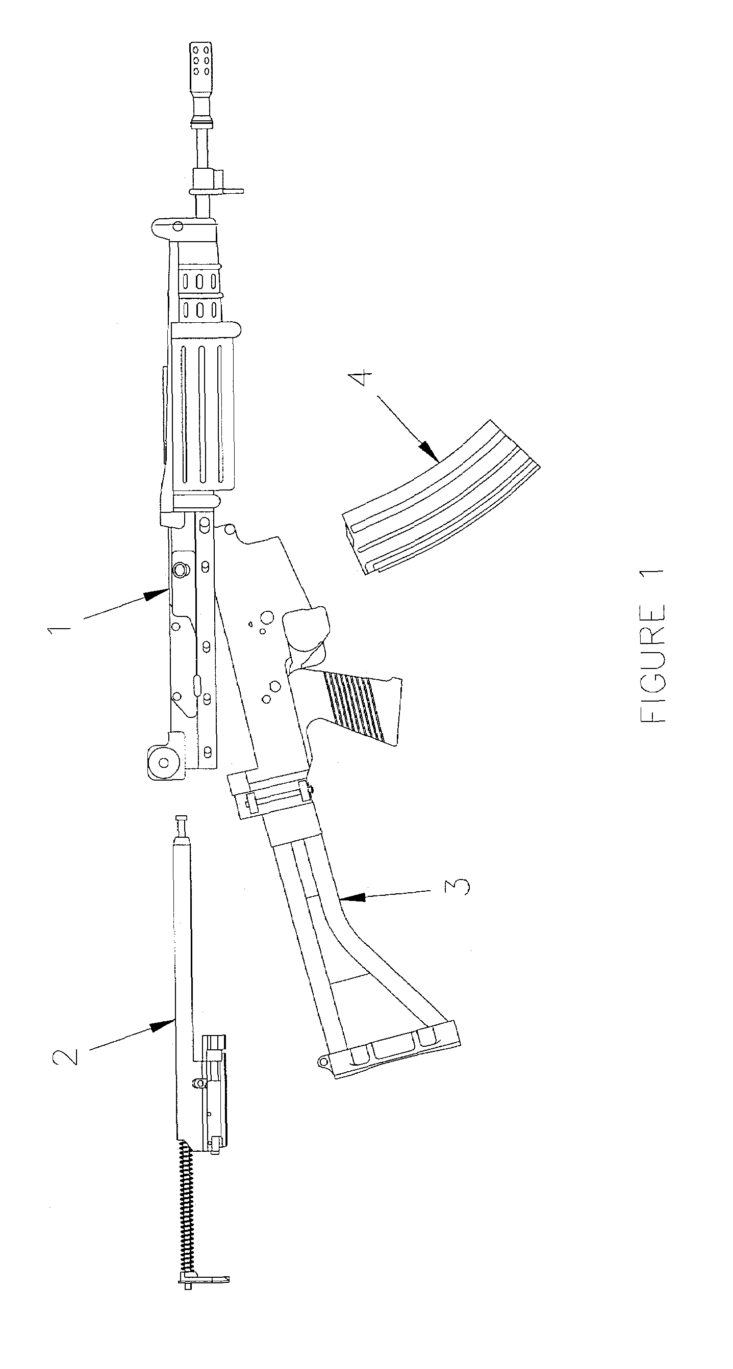
[0031]In FIG. 1 the four major groups of a typical prior art rifle in the class of 5.56 mm FNC gas-operated assault rifles are shown: barrel-receiver group 1, bolt carrier assembly 2, butt group 3, and magazine 4. According to the invention, in its conversion variant, only bolt carrier assembly 2 of the prior art will be altered to convert the prior art weapon to a training configuration that will fire a recoil-activating low-energy telescopically expanding training cartridge, as represented by U.S. Pat. No. 5,359,937 or 5,492,063 in a 5.56 mm version (the latter shown as training cartridge 26 in FIG. 6).

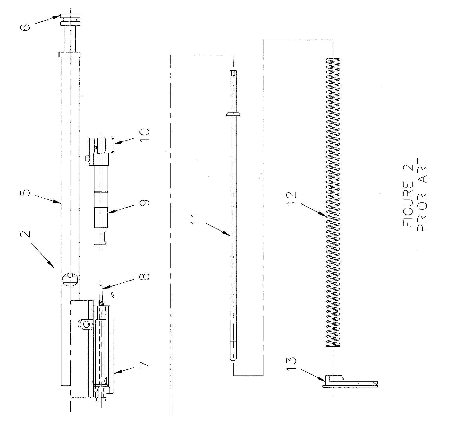
[0032]FIG. 2 is an exploded view of the prior art bolt carrier assembly 2 shown in FIG. 1. Its principal components are piston 5 comprising piston head 6, bolt carrier 7, firing pin 8, bolt 9 comprising lugs 10, guide rod 11, return spring 12, and stop plate 13. Stop plate 13 is anchored in / barrel-receiver group 1 (see FIG. 1). The bolt carrier assembly 2 is shown in FIG. 3 in its a...


PUM


Abstract

A blow-back operating automatic firearm has a sliding mass carried with its bolt carrier assembly to increase the dwell time of the bolt at the breech when the bolt is in battery position for firing. The sliding mass reduces the tendency of the bolt to bounce-off the head end of the seated cartridge, thereby reducing the risk that a misfiring will occur.

Description

FIELD OF INVENTION[0001]This invention relates to the field of automatic firearms incorporating a blow-back firing mechanism. In particular, it relates to means to attenuate rebound momentum of the bolt assembly. The invention is especially applicable for modifying automatic and semi-automatic firearms for training purposes to provide a weapon which has been converted to fire low-energy ammunition in an unrestrained, blow-back mode.BACKGROUND OF THE INVENTION[0002]In military and police firearms applications almost all of the ammunition consumed is used in training. For some training purposes, however, normal ammunition is not appropriate. An alternative type of ammunition, which has much lower energy and is represented by U.S. Pat. No. 5,359,937 (adopted herein by reference), fires a low-mass projectile relying on a special, low-energy cartridge designed to provide cycling of suitably modified, recoil-operated automatic and semi-automatic weapons. The cartridge case portion of this...

Claims


Application Information

Patent Timeline
IPC IPC(8): F41A33/00F41A3/54F41A5/00F41A5/02F41A3/00F41A3/12F41A3/70F41A11/02
CPCF41A3/12F41A3/54F41A3/70F41A11/02F41A21/36F41A25/00F41A25/10F41A25/12F41A35/00
Inventor DIONNE, SYLVAIN
Owner GENERAL DYNAMICS ORDNANCE & TACTICAL SYST CANADA VALLEYFIELD INC
Learn More