
Venous valvuloplasty device and method

a venous valve and valve body technology, applied in the direction of prosthesis, surgical staples, blood vessels, etc., can solve the problems of venular dilation, incompetence of the venous valve, adverse medical conditions, etc., and achieve the effect of promoting device longevity and function

Inactive Publication Date: 2005-08-23
TRICARDIA
View PDF12 Cites 140 Cited by
  • Summary
  • Abstract
  • Description
  • Claims
  • Application Information

AI Technical Summary

Benefits of technology

"The present invention provides a method and device for restoring the function of damaged valves in a vein. The device can be used percutaneously or surgically to restore competence to valves that have become incompetent due to dilation. The device consists of a ring that can be expanded to restore the vein to its original size and function. The ring can be made from a biocompatible material that does not interfere with the surrounding tissue and can be collapsible to avoid interfering with the circulatory system's natural pumping action. The device can also include a grabbing mechanism to hold the vein in place during the restoration process. The material of the device can be coated to enhance cellular ingrowth and prevent cell overgrowth. The invention provides a solution for restoring valve function in a vein and improving the hydrodynamics of the vein."

Problems solved by technology

As a majority of venous blood flow is against gravity while a person is standing, incompetent or destroyed venous valves often result in adverse medical conditions, especially in the lower extremities.
The leading cause of venous valve incompetence is venular dilation.
Another type of venous valve incompetence results from damaged cusps.
Reparation of damaged or otherwise incompetent venous valves has been largely limited to autograft procedures.
Autograft procedures, though effective, are undesirable as they require the location and excision of healthy, autologous vein segments from other areas of the body.
The excised segment must nearly match the size of the segment being replaced, making the location of a replacement vein a sometimes difficult task.
Developing a prosthetic or bioprosthetic valve that exhibits, if not improves upon, the functioning characteristics of healthy, natural valves is a task ripe with obstacles.
If the body rejects the valve, or if it malfunctions, many complications could arise, requiring a second surgery to remove the prosthetic valve and repair the vein segment using an alternative method.

Method used


Image

  • Venous valvuloplasty device and method
  • Venous valvuloplasty device and method
  • Venous valvuloplasty device and method

Examples


Embodiment Construction

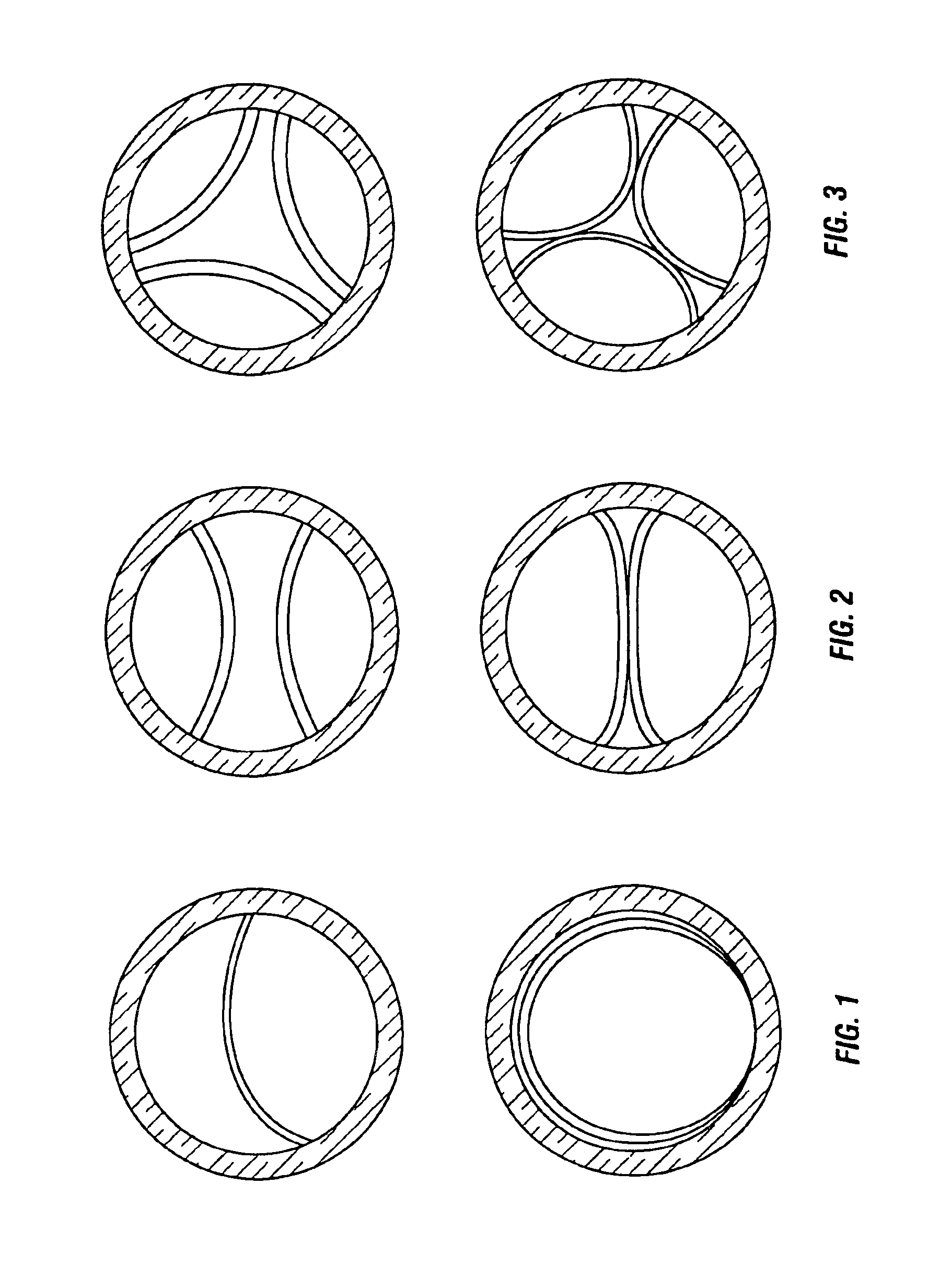
[0061]Referring now to the figures, and first to FIGS. 1 through 3, there are shown examples of unicuspid, bicuspid and tricuspid valves which have become so dilated that they have been rendered incompetent. Below each of the dilated valves, a healthy valve is shown for comparative reference.

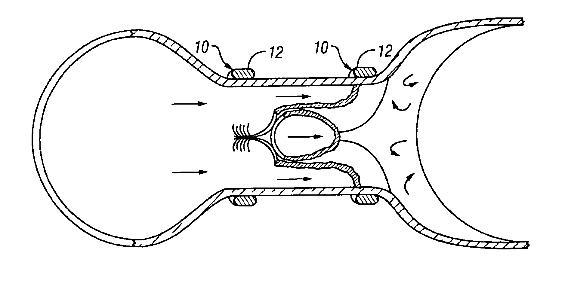
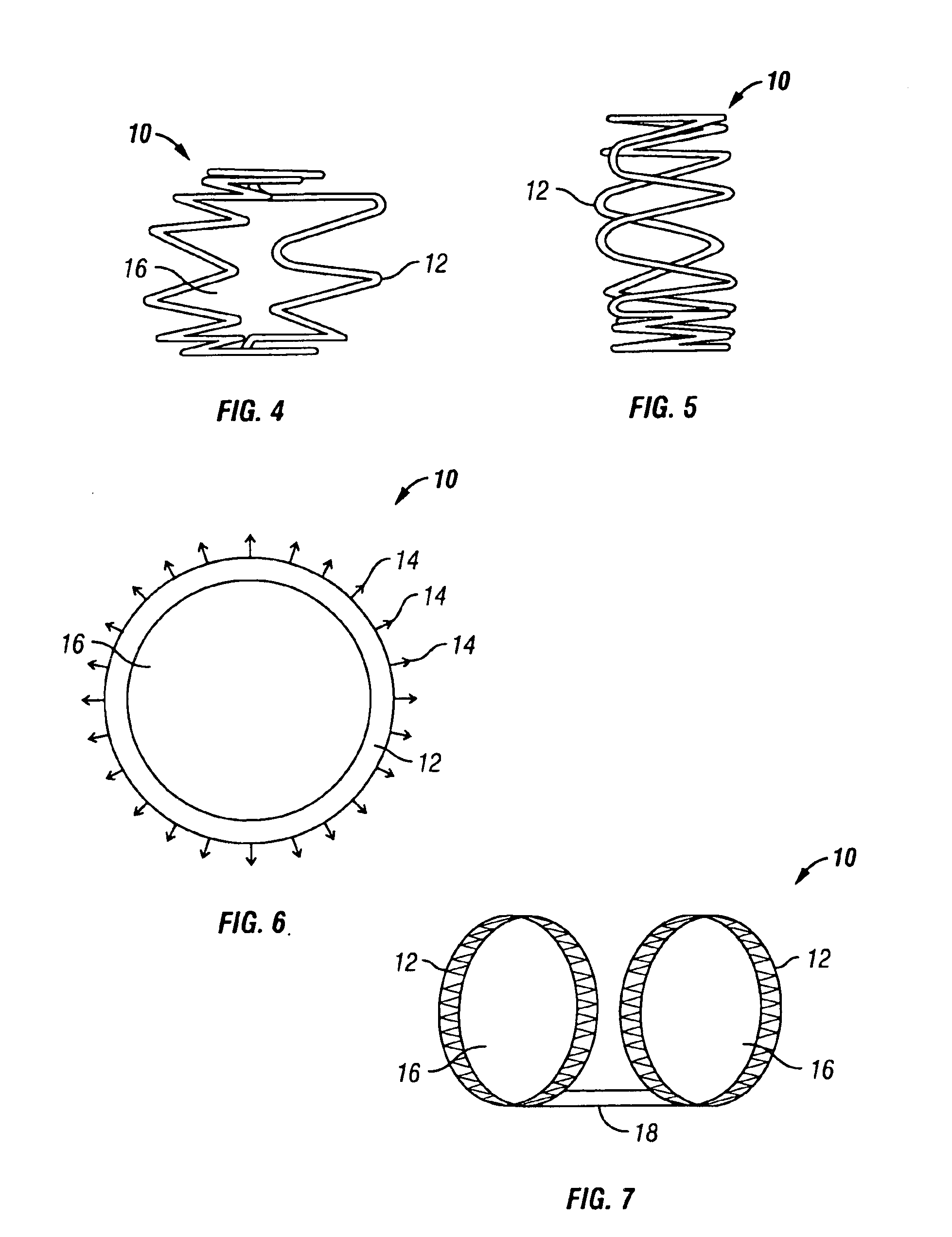
[0062]FIGS. 4-6 show a device 10 of the present invention, useable to reduce the diameter of a dilated vein such that competence may be restored. Device 10 generally comprises a support structure 12 and a grabbing mechanism 14 (shown only on FIG. 6 for clarity).

[0063]Support structure 12 is shown as a zig-zag patterned spring member curled to form a ring. The zig-zag patterned spring member allows energy to be stored in the bends of the spring when manipulated, and used to return the structure 12 to its original, ring-like configuration when released. One skilled in the art will realize that other structures also acceptably provide such a resilient characteristic. Examples include, but are not l...


PUM


Abstract

A device 10 and method for replacing or restoring competence to incompetent valves. The device 10 is inserted percutaneously or surgically and is preferably constructed of a material capable of promoting cellular ingrowth such that, eventually, native biologic tissue completely covers the device 10 insulating the blood flow therefrom. The material is preferably bioabsorbable over time, allowing the device to harbor the regeneration of a valve structure and to later become absorbed by the body. The device is sized and arranged to mimic the valve it is replacing or repairing.

Description

CROSS REFERENCE TO RELATED APPLICATION[0001]This application claims the priority of U.S. Provisional Ser. No. 60 / 236,501, filed on Sep. 29, 2000.BACKGROUND OF THE INVENTION[0002]The venous valves found throughout the venous system assist the flow of blood through the veins and returning to the heart by preventing blood flow reversal. As a majority of venous blood flow is against gravity while a person is standing, incompetent or destroyed venous valves often result in adverse medical conditions, especially in the lower extremities. For example, deep venous hypertension may occur and give rise to clots, lymphedema, skin discoloration, varicose veins and venous ulcers.[0003]The leading cause of venous valve incompetence is venular dilation. When a vein loses elasticity and becomes dilated, the valve cusps become too radially displaced from each other to coapt and prevent backflow. The cusps themselves, however, may not be damaged or stressed, such that restoring elasticity to the vein...

Claims


Application Information

Patent Timeline
Patent Type & Authority Patents(United States)
IPC IPC(8): A61F2/24A61B17/064
CPCA61F2/2412A61F2/2418A61F2/2475A61B17/064A61B2017/0641A61F2/2442A61F2/2445A61F2250/0031A61F2220/0016A61F2220/0008
Inventor SCHWARTZ, ROBERT S.VAN TASSEL, ROBERT A.
Owner TRICARDIA
Learn More