
Ultraviolet-and-ozone disinfection apparatus having improvement on disinfection effect

Inactive Publication Date: 2005-08-23
SENNO TECH
View PDF16 Cites 45 Cited by
  • Summary
  • Abstract
  • Description
  • Claims
  • Application Information

AI Technical Summary

Benefits of technology

[0018]The invention provides an improvement to prolong the time of exposure to the UV irradiation so as to achieve sufficient disinfection effect.
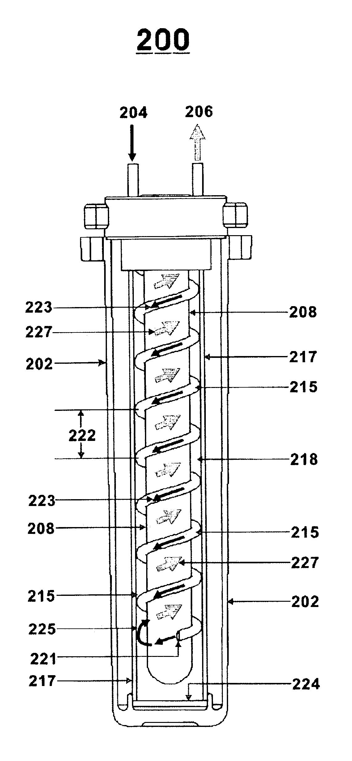
[0021]In view of the imperfection of the prior art, this invention suggests prolonging and improving the contact exposure time to achieve sufficient disinfection effect. So the object of this invention is to provide a dual mode disinfection apparatus and a special double spiral water flow design. The total distance of the flow can go above 120 cm, which is equal to 4 times the irradiation time and this greatly improves the disinfection effect.
[0022]It is therefore the main objective of the invention to provide a dual mode of disinfection apparatus and a special double spiral water flow design. That the route of the flow can be as high as 120 cm that is equivalent to 4 times the irradiation time greatly improves the disinfection effect.
[0023]To achieve the aforementioned objective, an embodiment of the invention provides a ultraviolet-and-ozone disinfection apparatus that includes a disinfection tank used as a housing and is having an water inlet and an water outlet, a mercury ultraviolet (UV) lamp for generating ultraviolet light, a quartz tube 208 enclosing the mercury UV lamp having air trapped between them being irradiated by the UV light to generate ozone gas, an ozone gas transmitting tube 216 inserted between them, a spiral water transmitting tube 215 surrounding the quartz tube 208 for homogenously mixing the ozone gas in the water to achieve sufficient disinfection effect, as well as a sleeve barrel 217 enclosing the spiral water transmitting tube 215. Following the impact force downstream through the tube, water out-flown from the spiral water transmitting tube 215 generates a reactive water flow that upstream back and flows along the outer surface of the spiral water transmitting tube 215 and through the space in the pitch of the spiral shape inside the sleeve barrel. Therefore, the water is all the way up exposed under the irradiation of the UV light to accomplish sufficient UV disinfection effect and reduce the excessive ozone that is harmful to human health. Finally, the disinfected water flows out of the water outlet to provide drinking water.
[0024]In another embodiments of the invention, one end of the sleeve barrel is closed off at the top of the disinfection tank and another end of the sleeve barrel is closed off at the bottom of the disinfection tank. Therefore, the sleeve barrel itself can replace the disinfection tank which houses the disinfection apparatus and therefore the disinfection tank can be removed.

Problems solved by technology

After the absorption of UV light by some protein substances reaches certain strength (dose), the cell membrane will be ruptured, causing the cell to die.
In addition, even if the UV dose is not high enough to cause immediate death of the cell, a lower dose of irradiation is sufficient to cause the microorganism to lose its breeding ability which makes people sick.
However, they fail to demonstrate their performance of effectively prolonging the irradiation time of UV light and the functioning time of ozone, as well as enhancing the basic requirement of disinfection by mixing and dissolving the ozone in the water homogeneously.
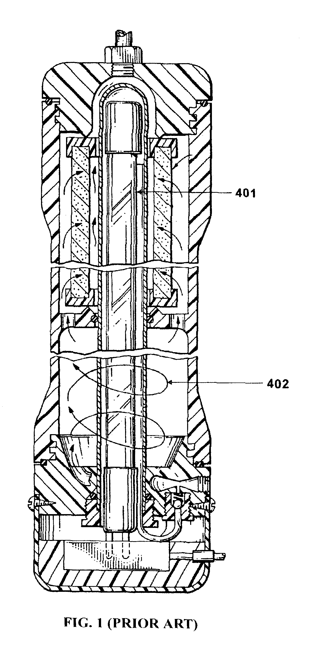
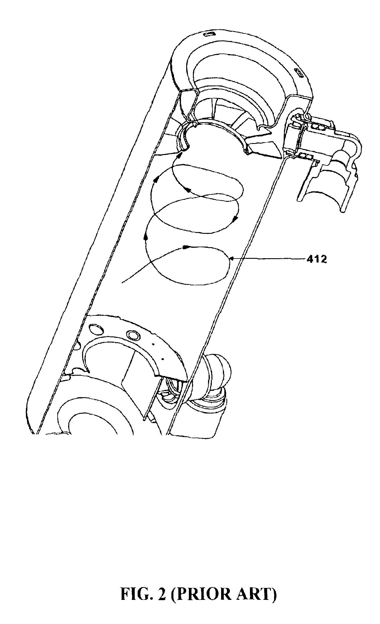
However, these patents are all simple designs of a spiral water column, and the exposure time to UV radiation is very limited.
This patent does not have any spiral design of water flow, so the disinfection effect is also very limited.
The spiral Teflon tube itself causes the UV irradiation to attenuate, and is therefore unable to achieve the disinfection objective.
Furthermore, the Teflon tube is lengthy and expensive, therefore is not economical.

Method used


Image

  • Ultraviolet-and-ozone disinfection apparatus having improvement on disinfection effect
  • Ultraviolet-and-ozone disinfection apparatus having improvement on disinfection effect
  • Ultraviolet-and-ozone disinfection apparatus having improvement on disinfection effect

Examples


Embodiment Construction

[0040]As shown in FIG. 5, the ultraviolet-and-ozone disinfection apparatus 200 of the invention that provides an improvement on disinfection effect is a part of a water treatment system. The water treatment system includes a filtering apparatus 100, a disinfection apparatus 200, and an ozone injection apparatus 300.

[0041]The ultraviolet-and-ozone disinfection apparatus 200 includes a disinfection tank 202, a mercury UV lamp 210, a quartz tube 208, an ozone transmitting tube 216, a spiral water transmitting tube 215, and a sleeve barrel 217.

[0042]As shown in FIGS. 5 and 7, the disinfection tank 202 is used as housing for the disinfection apparatus 200 and has a water inlet 204 and a water outlet 206. The mercury UV lamp 210 (FIG. 6) centered in the disinfection apparatus 200 is used to generate UV light after an electrical charge is applied. A wavelength of about 185 nm of the UV light can make the air generate ozone while a wavelength of about 254 nm of the UV light can be used for ...


PUM


Abstract

An ultraviolet-and-ozone disinfection apparatus 200 providing an improvement on disinfection, includes a disinfection tank 202, a mercury UV lamp 210 enclosed by a quartz tube 208 for generating UV light with air trapped between them undergoing UV irradiation to generate ozone, an ozone transmitting tube 216, a spiral water transmitting tube 215 wrapping around the quartz tube in a spiral manner to achieve sufficient disinfection by mixing ozone in water, a sleeve barrel enclosing the spiral tube. Along the entire flow path, water is exposed to UV radiation to achieve sufficient disinfection and reduce excessive ozone that is harmful to human health.

Description

CROSS REFERENCE TO RELEVANT APPLICATION[0001]This application is referred to a previous Taiwan application of serial no. 091133459 filed on Nov. 14, 2002. The applicant is also the inventor for both previous and present application.FIELD OF THE INVENTION[0002]The invention relates to an ultraviolet-and-ozone disinfection apparatus that improves the disinfection effect, and more particularly, a disinfection apparatus that provides double-spiral water flows that causes ozone gas and water to mix and dissolve thoroughly and homogenously. In addition, the water is exposed thoroughly under the irradiation of ultraviolet (UV) light to enhance the disinfection effect.BACKGROUND OF THE INVENTION[0003]In the conventional water treatment process, the water to be treated is exposed to the ozone generated by a mercury UV lamp. Another method is to expose an air stream to UV light irradiation causing the oxygen in the air to generate ozone. This ozonated air is then dissolved into the water to b...

Claims


Application Information

Patent Timeline
IPC IPC(8): C02F9/00C02F1/00C02F1/78C02F1/32
CPCC02F9/00C02F1/001C02F1/32C02F1/78C02F2201/003C02F2201/782C02F2201/784C02F2303/04C02F2301/026C02F2301/02
Inventor CHANG, STEVEN SHIH-YI
Owner SENNO TECH
Learn More