Optically generated isolated feedback stabilized bias
a technology of isolated feedback and bias, which is applied in the direction of pulse generator, pulse technique, instruments, etc., can solve the problems of increasing the cost of employing devices, reducing the reliability of employing devices, and sensitivity and resolution of detection equipment may be limited, so as to achieve stable output voltage
- Summary
- Abstract
- Description
- Claims
- Application Information
AI Technical Summary
Benefits of technology
Problems solved by technology
Method used
Image
Examples
example one
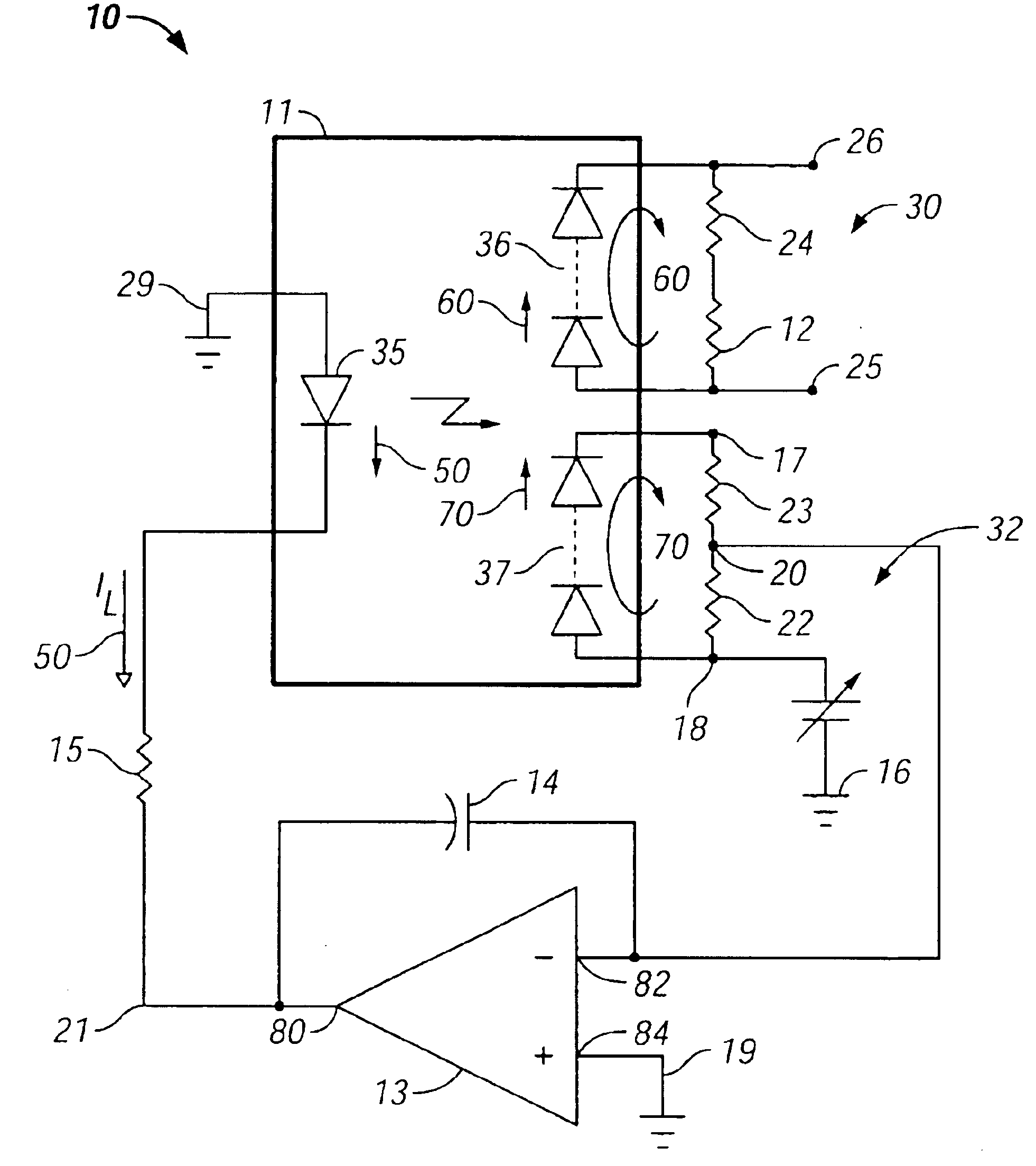
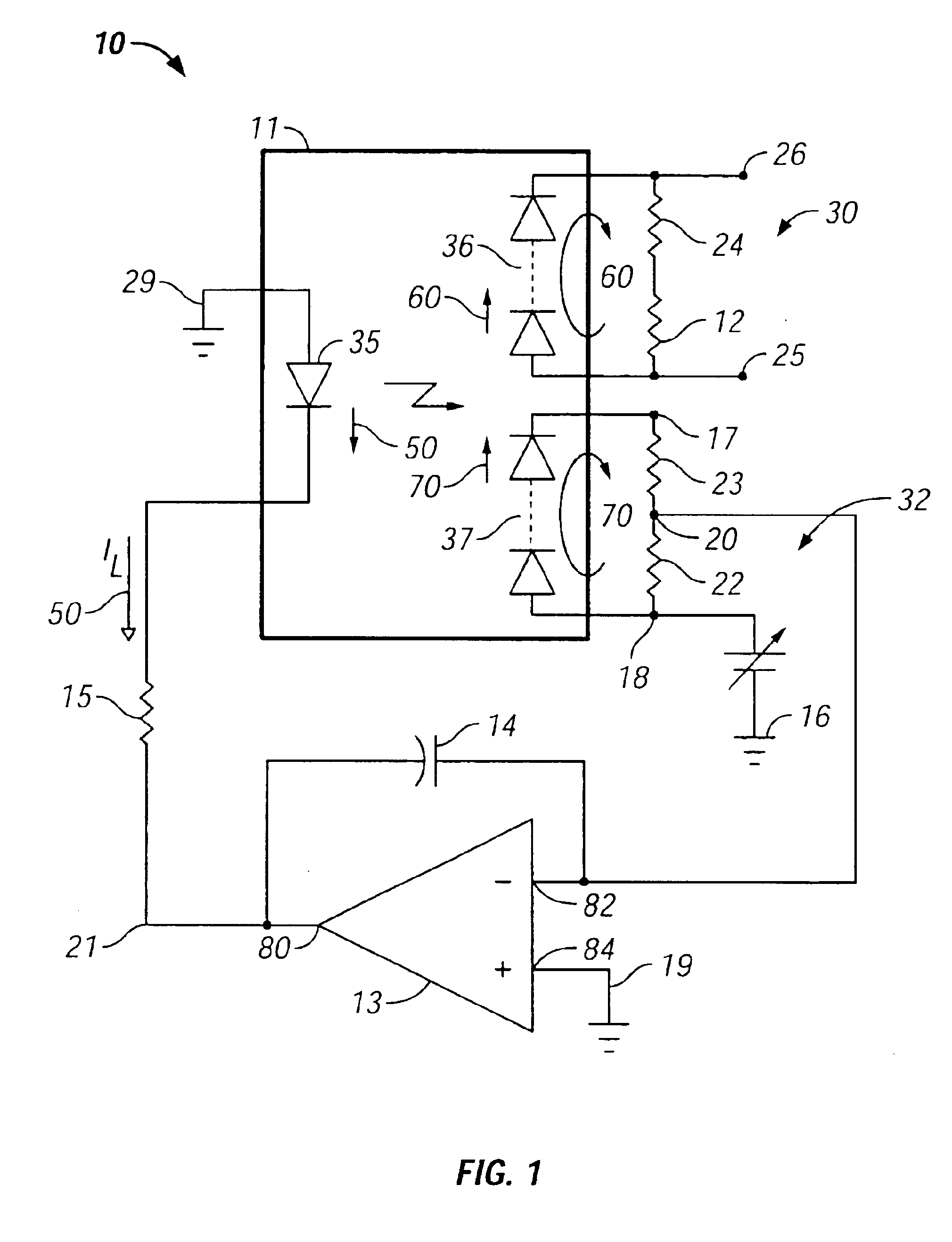
[0057]Assume that resistors 12, 22, 23 and 24, have equal value of 1.0×10⁶ ohms (1.0 M ohms); the amplifier gain A, is 1.0×10⁶; the voltage at node 18, set by reference source 16, is +10 volts; the current generated by the photovoltaic diodes is 10 microamperes; the voltage at node 17 is −10 volts; the voltage difference between nodes 25 and 26 is 20 volts; and the voltage at node 21 is −5 volts. The voltage at node 20 is then +5×10⁻⁶ volts, essentially zero for practical purposes. Since the current through resistor 22 into node 20 is equal to the current through resistor 23 out of node 20, no net current flows into (out of) inverting input 82 of amplifier 13, or through capacitor 14, via node 20. Since no current flows through capacitor 14 the voltage across capacitor 14 does not change and driving current 50 through resistor 15 does not change.
example two
orrection
[0058]Assume that an instantaneous variation in ambient conditions, e.g., temperature, occurs such that the voltage drop across resistors 22 and 23 (and thereby across resistors 12 and 24) is reduced by 1.0 volt. Since the voltage at node 18 is fixed at +10 volts by reference source 16, and the voltage at node 20 is essentially zero, the voltage at node 17 will thereby be −9 volts. The current through resistor 22, into node 20, will still be 10 microamperes; the current through resistor 23, out of node 20, will be 9 microamperes, and the net current into node 20, through capacitor 14, will thereby be 1 microampere. Since the voltage across a capacitor is proportional the integral of the current through it as:
V=(1 / C)∫i dt
[0059]the voltage across capacitor 14, will begin to change at a rate that satisfies the relation:
i=C dV / dt
where i is the current flowing through the capacitor, C, is the capacitance in Farads, and V is the voltage across the capacitor. (E.g., let the capaci...
PUM
 Abstract
Description
Claims
Application Information
 - R&D
- Intellectual Property
- Life Sciences
- Materials
- Tech Scout
- Unparalleled Data Quality
- Higher Quality Content
- 60% Fewer Hallucinations
Browse by: Latest US Patents, China's latest patents, Technical Efficacy Thesaurus, Application Domain, Technology Topic, Popular Technical Reports.
© 2025 PatSnap. All rights reserved.Legal|Privacy policy|Modern Slavery Act Transparency Statement|Sitemap|About US| Contact US: help@patsnap.com


