Liquid crystal display with a heat shield between the inverter and the backlight assembly

a technology of backlight assembly and liquid crystal display, which is applied in the field of liquid crystal display, can solve the problems of insufficient natural light, inability to perform displaying operation, and inability to use natural light for lcd, and achieve the effect of rapid discharge and blockage of heat generated, rapid discharge of heat, and increase of display area of lcd

Inactive Publication Date: 2005-08-23
SAMSUNG DISPLAY CO LTD
View PDF3 Cites 20 Cited by
  • Summary
  • Abstract
  • Description
  • Claims
  • Application Information

AI Technical Summary

Benefits of technology

[0021]It is another object of the present invention to rapidly discharge and block a large amount of heat generated from the inverter even though the display area of the LCD increases.
[0022]It is further another object of the present invention to rapidly discharge heat generated from the inverter so as not to exert an influence on all constructing elements of an LCD and also to rapidly remove leakage current generated from the inverter.
[0023]To achieve the aforementioned objects of the present invention, there is provided an LCD in which an LCD panel assembly controls a liquid crystal to display an image. A backlight assembly is provided with a lamp assembly, for supplying light to the LCD panel assembly, and a light uniformity-enhancing module, for improving uniformity of the light generated from the lamp assembly. A receiving container receives and fixes the LCD panel assembly and the backlight assembly. An inverter is disposed at an outer surface of the receiving container to supply power needed to drive the lamp assembly. A heat shielding means is disposed at the receiving container, corresponding to a portion between the inverter and the receiving container so as to intercept heat generated from the inverter and to prevent the heat from being transferred to the light uniformity-enhancing module.
[0024]According to another aspect of the present invention, there is provided an LCD in which an LCD panel assembly controls a liquid crystal to display an image. A backlight assembly is provided with a lamp assembly, for supplying light to the LCD panel assembly, and a light uniformity-enhancing module, for improving uniformity of the light generated from the lamp assembly. A receiving container receives and fixes the LCD panel assembly and the backlight assembly. A conductive chassis prevents the LCD panel assembly from being separated from the outside. An inverter is disposed at an outer surface of the receiving container to supply power needed to drive the lamp assembly. A heat shielding means shields heat generated from the inverter and prevents the heat from being transferred to the light uniformity-enhancing module. A ground member electrically connects the inverter and the heat shielding means.

Problems solved by technology

However, in the LCD, the liquid crystal that plays a conclusive role in performing the displaying operation cannot emit light by itself.
Therefore, the LCD has a disadvantage in that it is impossible to perform the displaying operation unless the light is externally supplied, even through the liquid crystal is precisely controlled.
Currently, the LCD using natural light has a fatal defect in that It is impossible to perform the displaying operation in a location that does not have enough natural light.
Although the CCFL type lamp has these advantages, however, since the lamp requires a very high driving voltage, it Is impossible to drive the lamp with only the low voltage used for controlling the liquid crystal of the LCD.
Since the inverter is generally formed on a printed circuit board, it is impossible to dispose the inverter at a side portion of the thin LCD.
However, when the inverter is disposed at the rear face of the LCD, as described above, the display quality degrades seriously at a screen portion of the LCD corresponding to the inverter.
The problem is caused by an operating characteristic of the inverter.
In concrete terms, the transformer as a core portion of the inverter generates excessive heat during the boosting operation, and the IC device also generates excessive heat during a data processing operation.
If the heat generated from the inverter is exerted for an extended time on the reflector panel, the Light guiding plate, optical sheets and LCD panel assembly, another problem arises, that is, lowering the optical characteristic according to the local expansion of the light guiding plate, the optical sheets as well as the reflector panel.
Therefore, another critical problem develops in that an inherent function of the liquid crystal is lost, so that the displaying operation can no longer be performed.
The problems generated at the inverter as described above became more serious since a displaying surface area of the LCD has been increased recently.

Method used


Image

  • Liquid crystal display with a heat shield between the inverter and the backlight assembly
  • Liquid crystal display with a heat shield between the inverter and the backlight assembly
  • Liquid crystal display with a heat shield between the inverter and the backlight assembly

Examples


first embodiment

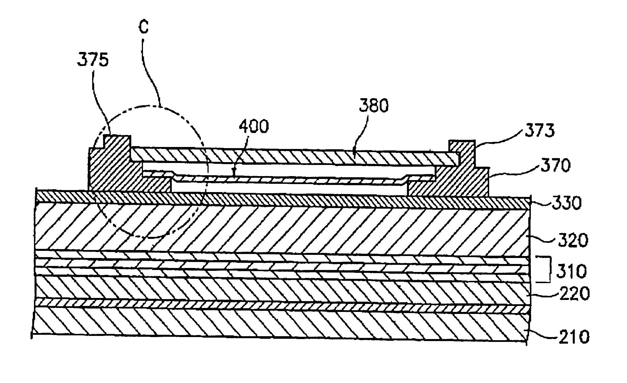
[0072]FIG. 6 is the heat shielding film 400 according to the present invention, and FIG. 7 is another embodiment, depicting an enlarged portion “C” from FIG. 5, showing a state that the heat shielding film 400 is applied to an LCD.

[0073]Referring to FIG. 6 or FIG. 7, the heat shielding film 400 has three or more layers. Hereinafter, the three layers are called a first shielding layer 410, an adhesive layer 420 and a second shielding layer 430.

[0074]Referring to FIG. 6, the first shielding layer 410 is comprised of an aluminum alloy or aluminum material having high heat conductivity and has a thin film structure, preferably having a thickness of about 0.1 mm. The first shielding layer 410 has a slightly larger surface area than the inverter module 380 while having a similar shape to the inverter module 380.

[0075]An adhesive having relatively low heat conductivity is entirely coated on a side of the first shielding layer 410 to form the adhesive layer 420. On an upper surface of the a...

second embodiment

[0076]FIGS. 8 and 9 show the present invention.

[0077]Referring to FIG. 8, the heat shielding film 400 of the embodiment also is comprised of three or more layers. A first shielding layer 440 is comprised of an aluminum thin film having high heat conductivity and, preferably, a thickness of about 0.1 mm. The first shielding layer 440 has a slightly larger surface area than the inverter module 380 while having a similar shape to the inverter module 380.

[0078]An adhesives having lower heat conductivity is entirely coated on a Side of the first shielding layer 440 to form the adhesive layer 450. On an upper surface of the adhesive layer 450, there is bonded a second shielding layer 460 having a thickness, preferably, of about 0.1 mm, which is the same as that of the first shielding layer 440, and has a similar shape to the first shielding layer 440. The second shielding layer 460 and a short jaw portion 374 are bonded to each other by a double-faced adhesive tape 401 attached along an e...

third embodiment

[0079]FIGS. 10 and 11 show the present invention.

[0080]Referring to FIG. 10, the heat shielding film 400 of the embodiment is comprised of a single shielding layer 470. That is, the shielding layer 470 has a similar shape to the inverter module 380. A planar surface area of the shielding layer 470 is slightly larger than that of the inverter module 380 to rapidly discharge the heat generated from the inverter module 380. The shielding layer 470 and the short jaw portion 374 are bonded to each other by a double-faced adhesive tape 401 attached along an edge of the shielding layer 470. Reference numerals 406, 407 designate stopper grooves to which a stopper 375 is coupled.

[0081]

TABLE 1TransformerIntegrated CircuitItemsTemperatureTemperatureTemperature of47.7° C.43.1° C.a bottom surface ofinverter module 380Comparison example44.0° C.42.7° C.First experiment35.1° C.33.5° C.Second experiment38.8° C.36.6° C.Third experiment38.5° C.36.0° C.

[0082]Table 1 above shows an experimental result i...


PUM

PropertyMeasurementUnit
thicknessaaaaaaaaaa
thicknessaaaaaaaaaa
temperatureaaaaaaaaaa

Abstract

There is disclosed a liquid crystal display (LCD) device that prevents degeneration of a displaying performance due to heat generated in the LCD. A heat shielding thin film of an aluminum-contained material, which is disposed in a receiving container, shields the heat additionally generated during a converting process of power for driving a lamp in an inverter module, thereby minimizing the heat to be transferred to a reflector panel. Therefore, the heat generated during a process of producing light is efficiently blocked and discharged, thereby minimizing the degeneration of displaying characteristic.

Description

BACKGROUND OF THE INVENTION[0001]1. Field of the Invention[0002]The present invention relates to a liquid crystal display (LCD), and more specifically, to a heat shielding film for preventing deformation of a reflecting plate and characteristic degeneration of liquid crystal due to heat generated from an inverter for driving a lamp that emits light necessary for a displaying operation and thus preventing partial or entire degeneration of displaying performance, and an LCD using the same.[0003]2. Description of the Related Art[0004]Generally, an LCD is defined as one of a flat panel display for displaying a desired character, image and moving picture using a physical and optical characteristic of liquid crystal.[0005]The LCD performs a displaying operation in a digital control method—in contrast with a conventional CRT (cathode ray tube) type display that performs the displaying operation in an analog control method. This offers an advantage of less weight and volume than the CRT typ...

Claims


Application Information

Patent Timeline
Patent Type & Authority Patents(United States)
IPC IPC(8): G02F1/13G02F1/133G02F1/1333G02F1/13357G09F9/00G09F9/35H04N5/66
CPCG02F1/133615G02F2001/133628G02F1/133628G02F1/1333
Inventor PARK, SANG-HOON
Owner SAMSUNG DISPLAY CO LTD
Why Eureka
Try Eureka