Thinner, lighter and lower aberration prisms for ophthalmic applications

a technology of aberration prisms and aberration lenses, applied in the direction of instruments, mountings, spectacles/goggles, etc., can solve the problem of impracticality of thick prisms for spectacle use, and achieve the effect of improving optical performance and reducing the thickness of composite prisms

Inactive Publication Date: 2005-08-23
PANDYA RANJANA
View PDF8 Cites 14 Cited by
  • Summary
  • Abstract
  • Description
  • Claims
  • Application Information

AI Technical Summary

Benefits of technology

[0014]The dramatic reduction in the thickness of composite prisms is also accompanied by a significant improvement in optical performance. This improvement has been demonstrated by measurements with optical instruments as well as tests on human subjects. Visual acuity of an ophthalmic device is usually measured in terms of Snellen acuity, whi...

Problems solved by technology

ical. Very thick prisms are impractical for use in spectacles beca...

Method used


Image

  • Thinner, lighter and lower aberration prisms for ophthalmic applications
  • Thinner, lighter and lower aberration prisms for ophthalmic applications
  • Thinner, lighter and lower aberration prisms for ophthalmic applications

Examples


example 1

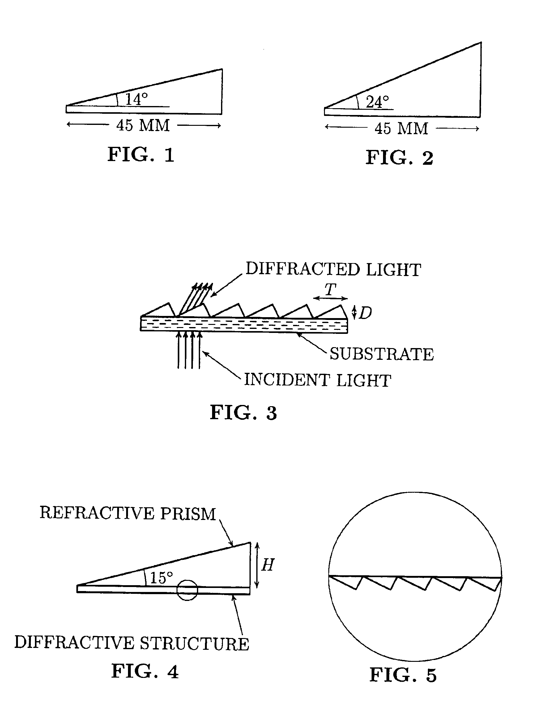
[0036]A composite prism of 23 p.d. was made and tested. This prism was similar to the prism shown in FIG. 1. The high index refractive prism component of the composite prism was made using the glass SFL-6 with a refractive index of 1.8 and Abbe number of 26. This glass was manufactured by the Ohara company. A refractive SFL-6 prism with a prism angle of 14 degrees produced about 21 p.d. prismatic power. A low blaze angle blazed grating with a blaze angle of 2.3 degree and a groove density of 35 grooves / mm produced additional prismatic power of about 2 p.d., thus making the total prism power of the refractive and diffractive components slightly over 23 p.d. It is important to note that a standard ophthalmic acrylic prism of similar thickness would have produced only 13 p.d. prismatic power. The diffractive structure was replicated from a grating master using thermally cured epoxy on a 1.5 mm thick, transparent BK-7 glass substrate, and was similar to that shown in FIG. 3. The grating...

example 2

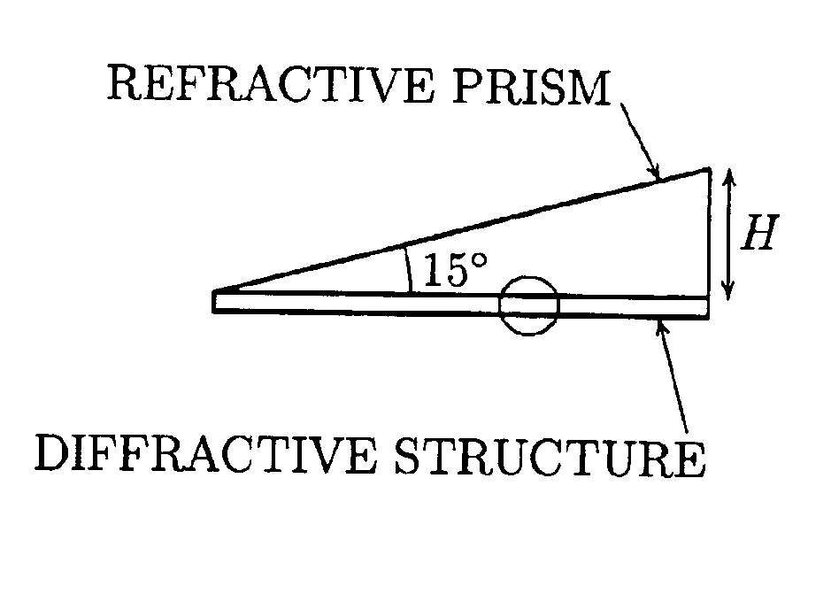
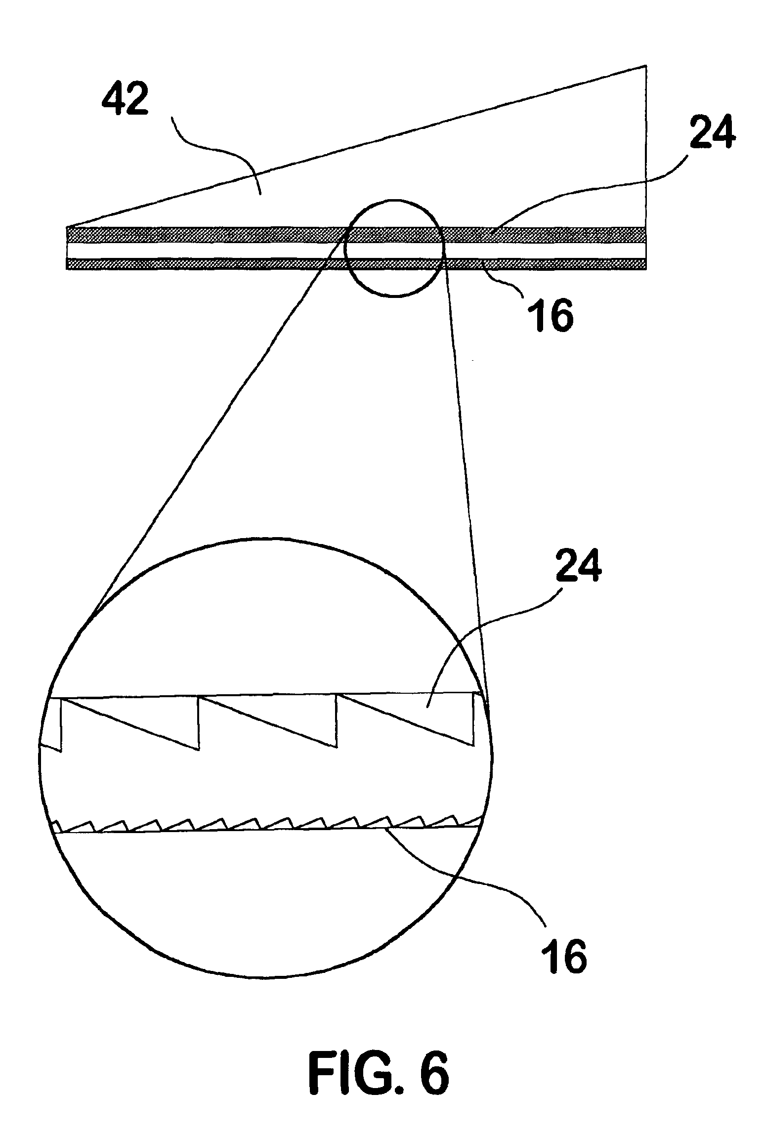
[0038]Instead of replicating the diffractive structure on a separate transparent substrate as was the case in example 1, the diffractive structure in this example was directly replicated onto the high index refractive prism. This method avoids the use of a separate substrate, thus reducing the thickness of the composite prism to the least possible. Additional reflections arising from the use of another surface are also eliminated. For this example, a high index prism with a prism angle of 15 degrees was made using High-Lite glass. This glass has a refractive index of 1.7 and is manufactured by the Schott company. A blazed grating with a blaze angle of 2.3 degree, a groove density of 35 grooves / mm and with its highest efficiency at a wavelength of 570 nm, was then replicated on the base face of the high index refractive prism as shown in FIG. 4. The orientation of diffractive structure grooves is shown in FIG. 5. The total prismatic power of the composite prism was about 22 p.d. An o...


PUM


Abstract

Novel optical devices, which are referred to as composite prisms in this document, have been designed, produced and tested. They have the potential to be useful for a number of vision related applications. For high prism diopter (15 prism diopters or more), composite prisms have resulted in thinner, lighter and lower aberration optical devices than the standard ophthalmic prisms currently in use. They also offer significantly better optical quality than the Fresnel press-on prisms which are also used to correct several ophthalmic disorders.

Description

CROSS-REFERENCE TO RELATED APPLICATIONS[0001]In this non-provisional patent application, the applicant would like to claim the benefit of an earlier provisional patent application No. 60 / 313,534 filed on Aug. 20, 2001 (8 / 20 / 01) with the US Patent and Trademark Office (USPTO). The corresponding provisional patent application contains drawings and a significant part of the present patent application. The applicant has also filed a disclosure document no. 494556, dated Jun. 1, 2001 with the USPTO. The disclosure document contains a brief description of the material in this patent application.REFERENCE TO A MICROFICHE APPENDIX[0002]Not Applicable.FEDERALLY SPONSORED RESEARCH OR DEVELOPMENT[0003]Funds from the federally sponsored Small Business Innovation Research (SBIR) program, which were awarded as SBIR phase I grant #1R43 EY10279-01A4 and SBIR phase II grant #2R44 EY 10279-02 were used to develop the ideas and devices mentioned in this invention. However, the awardee organization ret...

Claims


Application Information

Patent Timeline
IPC IPC(8): G02C7/14G02C7/00
CPCG02C7/14
Inventor PANDYA, RANJANA
Owner PANDYA RANJANA
Why Eureka
Try Eureka