On-chip temperature measurement technique

a technology of temperature measurement and on-chip, applied in the field of integrated circuits, can solve the problems of skewing the system clock of the microprocessor, adversely affecting component performance, increasing the temperature generated by such circuits, etc., and achieves the effects of reducing risk, reducing area, and reducing band gap circuitry

Inactive Publication Date: 2005-08-23
ORACLE INT CORP
View PDF5 Cites 35 Cited by
  • Summary
  • Abstract
  • Description
  • Claims
  • Application Information

AI Technical Summary

Benefits of technology

[0006]The present invention provides a temperature monitoring solution that eliminates the need for bipolar devices. In the present invention, a temperature-dependent voltage is generated using a long-channel MOS transistor configured in a diode connection or a similar component. In one embodiment of the invention, the diode drives a linear regulator which provides an input to a voltage-controlled ring oscillator. In alternate embodiments of the invention, the diode is connected directly to the ring oscillator.
[0009]The method and apparatus of the present invention represents an improvement over the prior art because it relies on a fixed system clock instead of a complex analog circuit. In addition, the present invention eliminates band gap circuitry currently used in most thermal sensing devices to provide a temperature-independent reference. The present invention offers numerous advantages over the prior art, including reduced area, reduced risk, and greater accuracy, as will be understood by those of skill in the art.

Problems solved by technology

It is well known that the increase in the number of circuit components placed on integrated circuits has led to an increase in temperature generated by such circuits.
Temperature gradients across the dies of conventional high performance very large scale integration (VLSI) components, such as a microprocessor, can adversely affect component performance.
For example, a temperature variation between two clock driver circuits within a microprocessor often results in a skew in the system clock of the microprocessor.
Moreover, the die of the microprocessor may reach an unacceptable temperature that causes the microprocessor to malfunction or stop functioning.
The base-emitter voltage of bipolar devices, however, does not scale in the same manner as the threshold of metal oxide semiconductor transistors used in many current integrated circuits.

Method used


Image

  • On-chip temperature measurement technique
  • On-chip temperature measurement technique
  • On-chip temperature measurement technique

Examples


Embodiment Construction

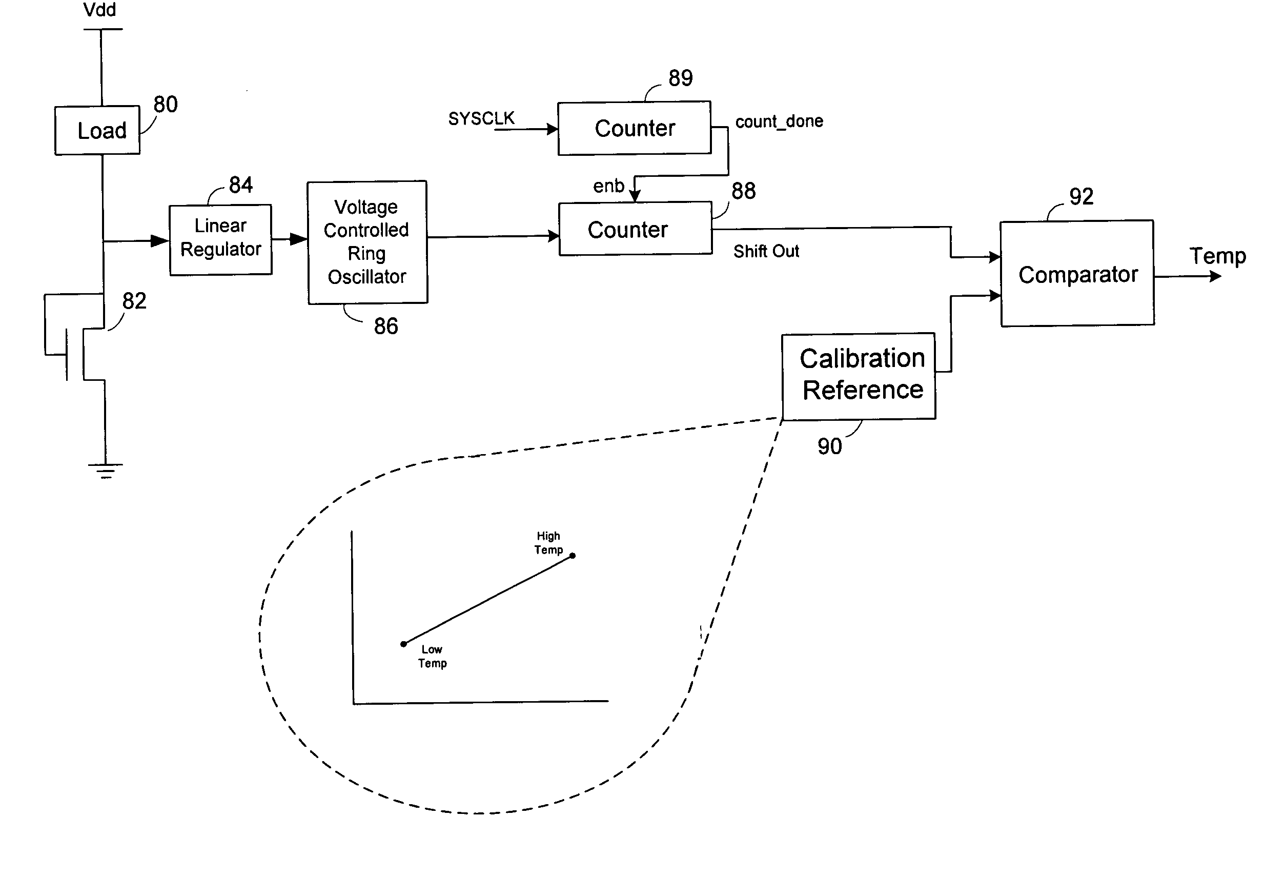
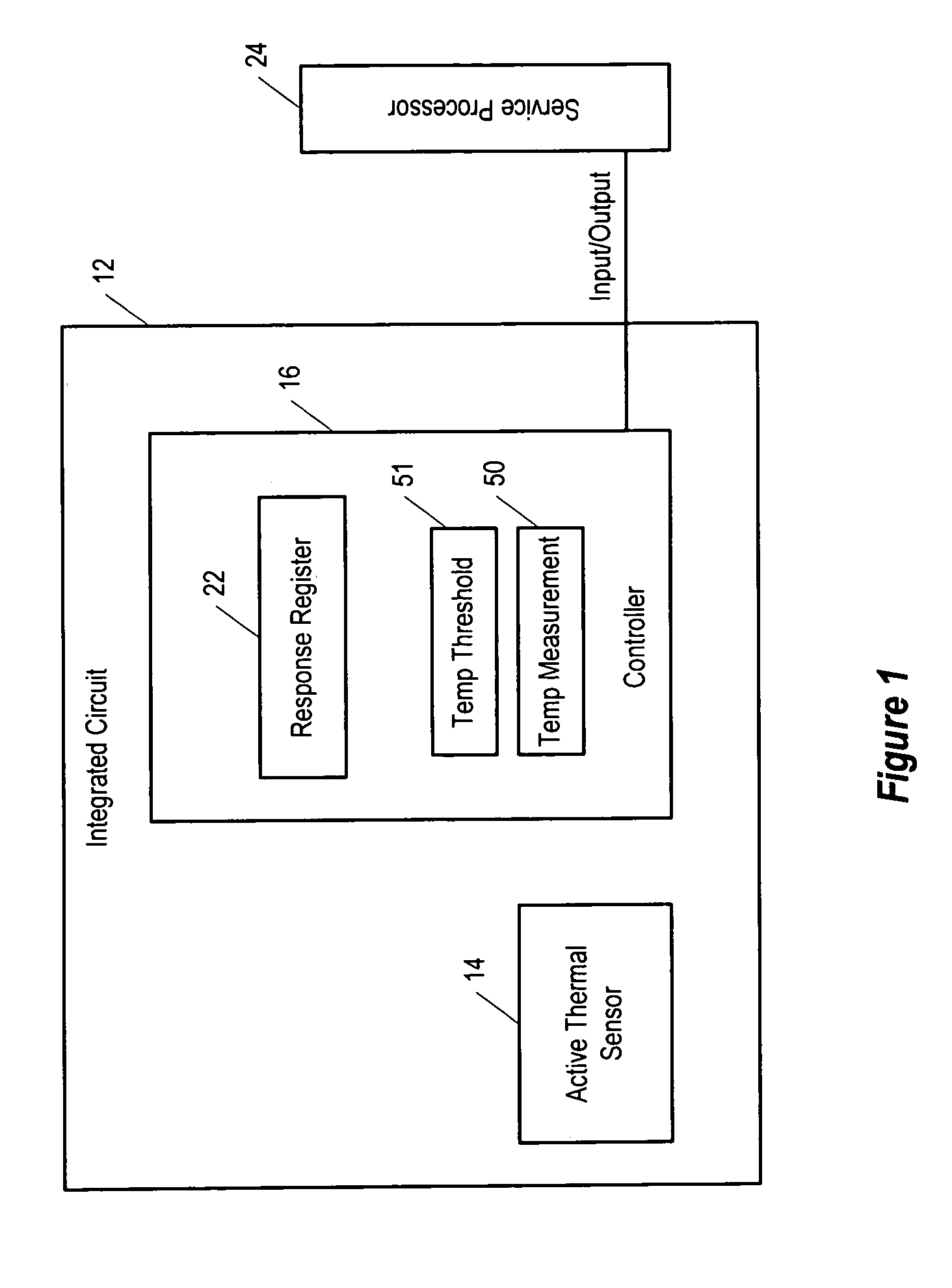
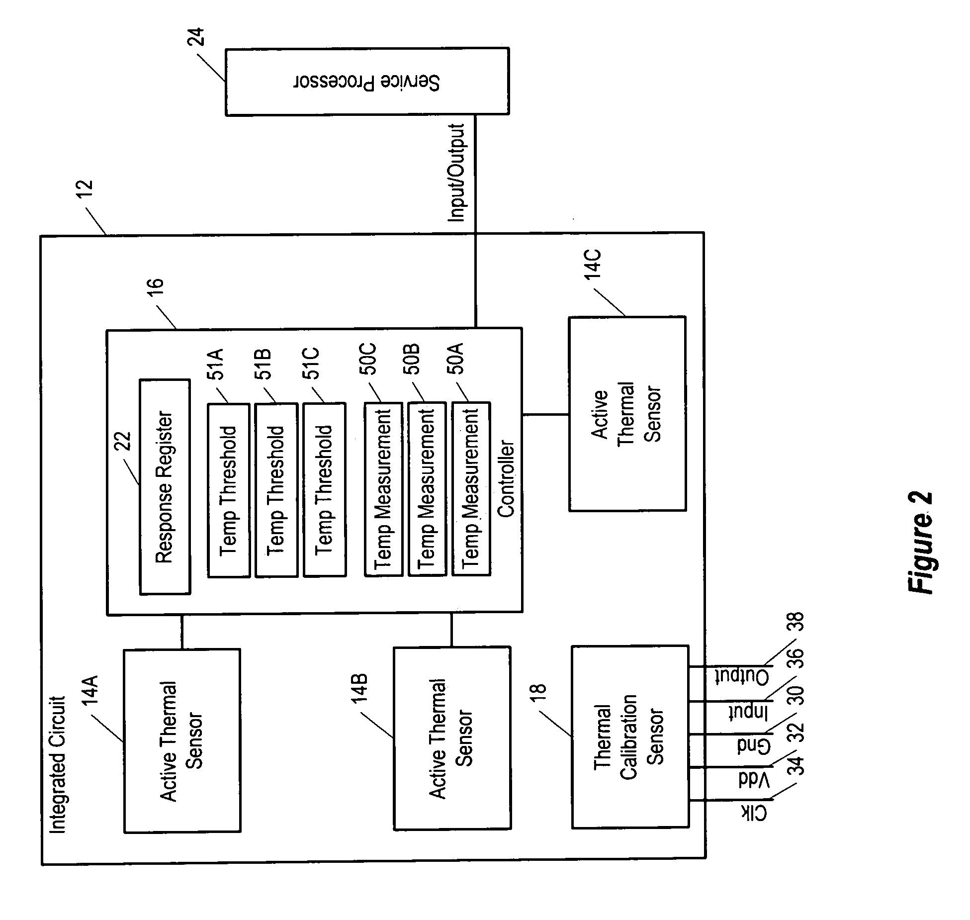
[0016]The illustrative embodiment of the present invention provides a temperature monitoring system for an integrated circuit that provides one or more die temperature measurements of the integrated circuit to actively monitor and control the die temperature across the integrated circuit. In the illustrative embodiment, the temperature monitoring system includes at least one thermal sensor that is configured as an active device to sense a die temperature of an integrated circuit and a controller to determine if the temperature sensed by the active thermal sensor indicates an undesirable temperature condition in the integrated circuit.

[0017]In the illustrative embodiment, the temperature monitoring system is attractive for use in integrated circuits that require highly accurate and reliable die temperature measurements. Each thermal sensor in the system operates in an independent manner, that is, without disturbing other operations being concurrently performed in the integrated circu...


PUM

PropertyMeasurementUnit
voltagesaaaaaaaaaa
temperatureaaaaaaaaaa

Abstract

A temperature monitoring technique that eliminates the need for bipolar devices. In one embodiment of the present invention, a long-channel MOS transistor is configured in a diode connection to sense change in temperature. The diode drives a linear regulator and an oscillator. The oscillator in turn drives a counter, which counts pulses for a fixed period of time. The system clock on the chip is used as a temperature-independent frequency to generate a count. The temperature-dependent frequency is counted for a fixed number of system clock cycles. The present invention eliminates band gap circuitry currently used in most thermal sensing devices to provide a temperature-independent reference.

Description

TECHNICAL FIELD OF THE INVENTION[0001]The present invention generally relates to integrated circuits, and more particularly, to a system and method to monitor the temperature of integrated circuits.BACKGROUND OF THE INVENTION[0002]As techniques for fabricating integrated circuits have advanced, the number of circuit components in integrated circuits has increased dramatically. It is well known that the increase in the number of circuit components placed on integrated circuits has led to an increase in temperature generated by such circuits.[0003]Temperature gradients across the dies of conventional high performance very large scale integration (VLSI) components, such as a microprocessor, can adversely affect component performance. For example, a temperature variation between two clock driver circuits within a microprocessor often results in a skew in the system clock of the microprocessor. Moreover, the die of the microprocessor may reach an unacceptable temperature that causes the ...

Claims


Application Information

Patent Timeline
Patent Type & Authority Patents(United States)
IPC IPC(8): G01K15/00
CPCG01K15/00
Inventor GAUTHIER, CLAUDE R.YEE, GIN S.
Owner ORACLE INT CORP
Why Eureka
Try Eureka