System and method for polymer filter cake removal

Inactive Publication Date: 2005-08-30
ENCANA OIL & GAS USA +1
View PDF14 Cites 31 Cited by
  • Summary
  • Abstract
  • Description
  • Claims
  • Application Information

AI Technical Summary

Benefits of technology

[0019]In operation according to preferred embodiments of the present invention, polymeric residue is removed to reduce formation damage in a variety of ways. For example, by having the breaker on the outside of the polymer filter cake, as the breaker flows through the polymer filter cake the breaker removes the polymer filter cake, thus exposing more formation that can contribute to hydrocarbon production. Moreover, the flow path of breaker according to the present invention also results in exc

Problems solved by technology

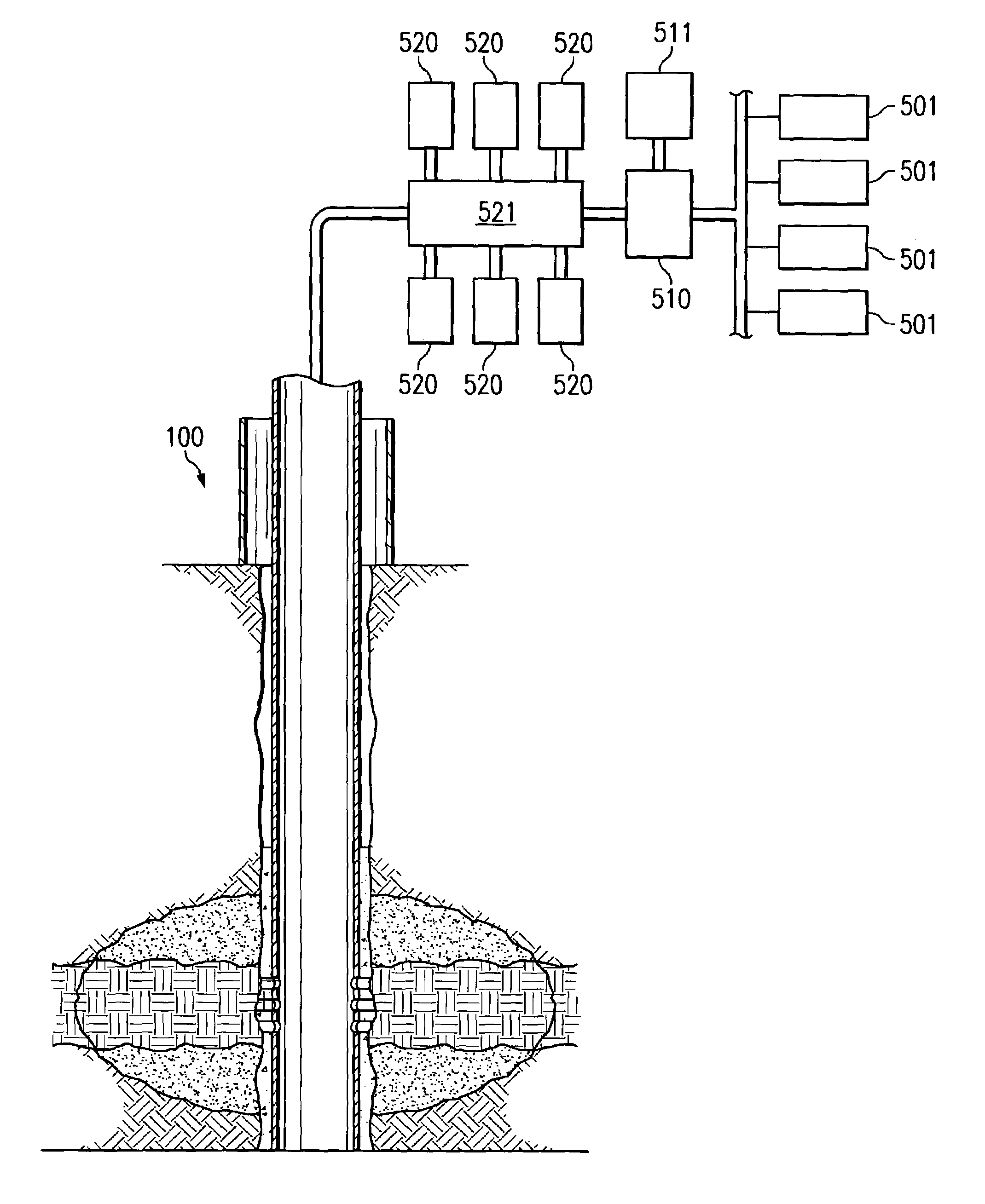
Thereafter, fracturing fluids, such as viscous and/or non-viscous fluids with or without proppants suspended therein, may be injected down the wellbore casing at sufficient volume and pressure to interface with the hydrocarbon producing formations, via the aforementioned perforations, and cause stress fracturing thereof.
Although providing increased viscosity as compared to non-viscosified base fluids, in many cases linear gels have insufficient viscosity to adequately transport proppants.
The aforementioned polymer filter cake is generally very tough and often is substantially impermeable to fluids.
The formation of polymer filter cake is a serious problem in the production of hydrocarbons from a well suffering from such damage as the gel residue plugs up porous hydrocarbon producing media reducing or preventing the flow of the desired hydrocarbons.
However, although providing improved viscosity, and therefore often providing better distribution of proppants, polymer filter cake residue resulting from cross-linked gels is often less fluid permeable and typically more difficult to remove.
However, it is very difficult to break or degrade the polymer filter cake because it is difficult to get breakers to the polymer filter cake material in sufficient quantities to cause the polymer filter cake to be degraded or removed.
For example, it is very difficult to get good communication between breaker pumped into the well during the fracturing process and the polymer filter cake as the breaker spends itself on the fracturing fluid gel, leaving very little breaker to react with the polymer filter cake.
However, the amount of breaker that may be utilized is limited because if too much breaker

Method used


Image

  • System and method for polymer filter cake removal
  • System and method for polymer filter cake removal
  • System and method for polymer filter cake removal

Examples


Example

[0027]Directing attention to FIG. 1, a well, such as that which may be utilized in the production of hydrocarbons from reservoirs disposed deep within the Earth, is shown generally as well 100. Well 100 of the illustrated embodiment includes wellbore 110 which has been bored into the various Earthen strata, including hydrocarbon bearing pay-strata 130, in a conventional manner as is well known in the art. Wellbore 110 has a continuous pipe casing, shown as casing 120, disposed therein. In typical fashion, cement 111 is shown disposed annular to casing 120 to provide hydraulic isolation.

[0028]Well 100 of FIG. 1 is shown in a substantially pre-completion state, i.e., the well has not been substantially processed to provide for commercial production of hydrocarbons from pay-strata 130. Although not yet at a completion state, well 100 of FIG. 1 does show the results of an early completion step in perforations, shown as perforations 121, disposed in casing 120 corresponding to pay-strata...


PUM


Abstract

Embodiments provide systems and methods in which a non-viscous fluid, having a heavy concentration of an appropriate breaker, is pumped into a well in front of viscosified fluid, such as a cross-linked polymeric fracturing fluid, to saturate permeable media with a breaker agent. When a polymer filter cake is subsequently formed on the surfaces of the media the breaker is provided good communication with the polymer filter cake for its breakdown and removal. Communication between the breaker and the polymer filter cake is substantially controlled by an operator in that the breaker remains saturated in the permeable media until such time as the operator decreases hydraulic pressure within the well to a point at which the hydraulic pressure of the media forces the breaker back into the well.

Description

TECHNICAL FIELD[0001]The present invention relates generally to oil and gas well completion operations and, more particularly, to providing efficient removal of polymer or filter cake formed with respect to such completion operations.BACKGROUND OF THE INVENTION[0002]In preparing a well, such as those bored to produce hydrocarbons, for increased production a process of hydraulic fracturing is often used. For example, hydraulic fracturing may be used to extend the effective radius of a wellbore and, thereby, provide increased surface areas, such as to expose more surface area of a hydrocarbon bearing formation and facilitate an increase in the flow of hydrocarbons from the well.[0003]Hydraulic fracturing involves pumping fluids into a well with enough injection rate and pressure to create a fracture in subterranean formations. For example, a casing disposed in a wellbore may be perforated at a depth or depths corresponding to hydrocarbon producing formations. Thereafter, fracturing fl...

Claims


Application Information

Patent Timeline
IPC IPC(8): E21B43/27E21B43/25E21B37/06E21B43/267
CPCE21B37/06E21B43/267
Inventor RAINBOLT, MICHAEL F.TULLIS, ANDREW W.
Owner ENCANA OIL & GAS USA
Why Eureka
Try Eureka