
Thrombolysis device

a thrombolysis device and thrombolysis technology, applied in the field of intravascular thrombolysis, can solve the problems of thrombosis, thrombosis, and life-threatening clots in blood vessels, and none is particularly adapted for thrombolysis, so as to facilitate the dislocation, and facilitate the dissolution of thrombosis

Inactive Publication Date: 2005-08-30
TYCO HEALTHCARE GRP LP
View PDF76 Cites 104 Cited by
  • Summary
  • Abstract
  • Description
  • Claims
  • Application Information

AI Technical Summary

Benefits of technology

The present invention provides a motion catheter that can be used to remove blockages in the body. The catheter can be placed in a blocked lumen and can use its motion alone or in combination with the dispensing of a medicament to dissolve the blockage. The catheter can be placed using fluoroscopy or ultrasound and can be used to dissolve blood clots or thrombi with or without the use of a lysing agent. The catheter's motion helps to dislodge or dissolve the blockage by mechanical agitation. The invention provides a convenient and effective tool for removing blockages in the body.

Problems solved by technology

It is well known that the formation of thrombi (clots) in blood vessels is a serious medical malady.
All thrombi need not be treated interventionally, but in many instances thrombi do, in fact, become life threatening and require removal or at least reduction in size.
None are particularly adapted for removing thrombi.
The use of laser catheters for treatment of thrombi is not uncommon, and significant damage to vessels during this treatment have been reported.
Significant problems such as hemorrhagic complications, early rethrombosis, prolonged infusion times, costs, significant failure rates, etc., are persistent problems with the use of these pharmaceutical agents.
But even this approach requires excessive time and drug amount.
In addition, the use of pulsatile injections of thrombolytic agents may result in pieces of the clot fracturing off from the main body of the clot and causing an embolism which is a danger faced by interventionalists performing this procedure.
Further, Stiles teaches the use of vibrational frequencies in the range “of at least 60 KHz.” The vibrational frequency employed to effect lysis is an important issue.
Wherever the probe tip touches the surrounding aspiration tube walls and / or aspirate, energy will be lost due to heating.
Thus, it is difficult or impossible to control the amount of ultrasonic vibratory energy reaching the tip of the probe.
Depending on the amount of loss of ultrasonic vibrational energy that occurs along the length of the probe (which, of course, depends on the amount of aspirate in the aspirator tube and the amount of mechanical contact between the probe and the surrounding walls) the energy actually delivered to tissue at the probe tip may either ablate or weld tissue, emulsify an obstruction or be insufficient to have any effect on an obstruction.
That is, the undesirable coupling of vibratory energy out of the Stiles' probe is unpredictable.

Method used


Image

  • Thrombolysis device
  • Thrombolysis device
  • Thrombolysis device

Examples


example

[0043]To prove evaluate the effectiveness of the present invention, an in vitro experiment was performed to evaluate the advantage, if any, of using the motion catheter to disperse clots rather than existing technology. Blood clots were created in a test tube. The weight of each clot was measured prior to experimentation. The clots were then treated with urokinase at a rate of 5000 IU / ml for 5 minutes to a total of 15,000 IU. The clot (thrombus) weights were measured initially and finally to determine the amount of lysing that had taken place. One of the groups (Group 1) was used as a control. Nothing was done to the Group 1 thrombi except initial and final weighing. Another group (Group 2) was treated with the same amount of lysing agent, but the lysing agent was dispersed through the motion catheter while the catheter was being very slowly vibrated, the catheter was placed proximal to the clot in similar fashion as was the aforementioned group. In Group 3, the motion catheter was ...


PUM


Abstract

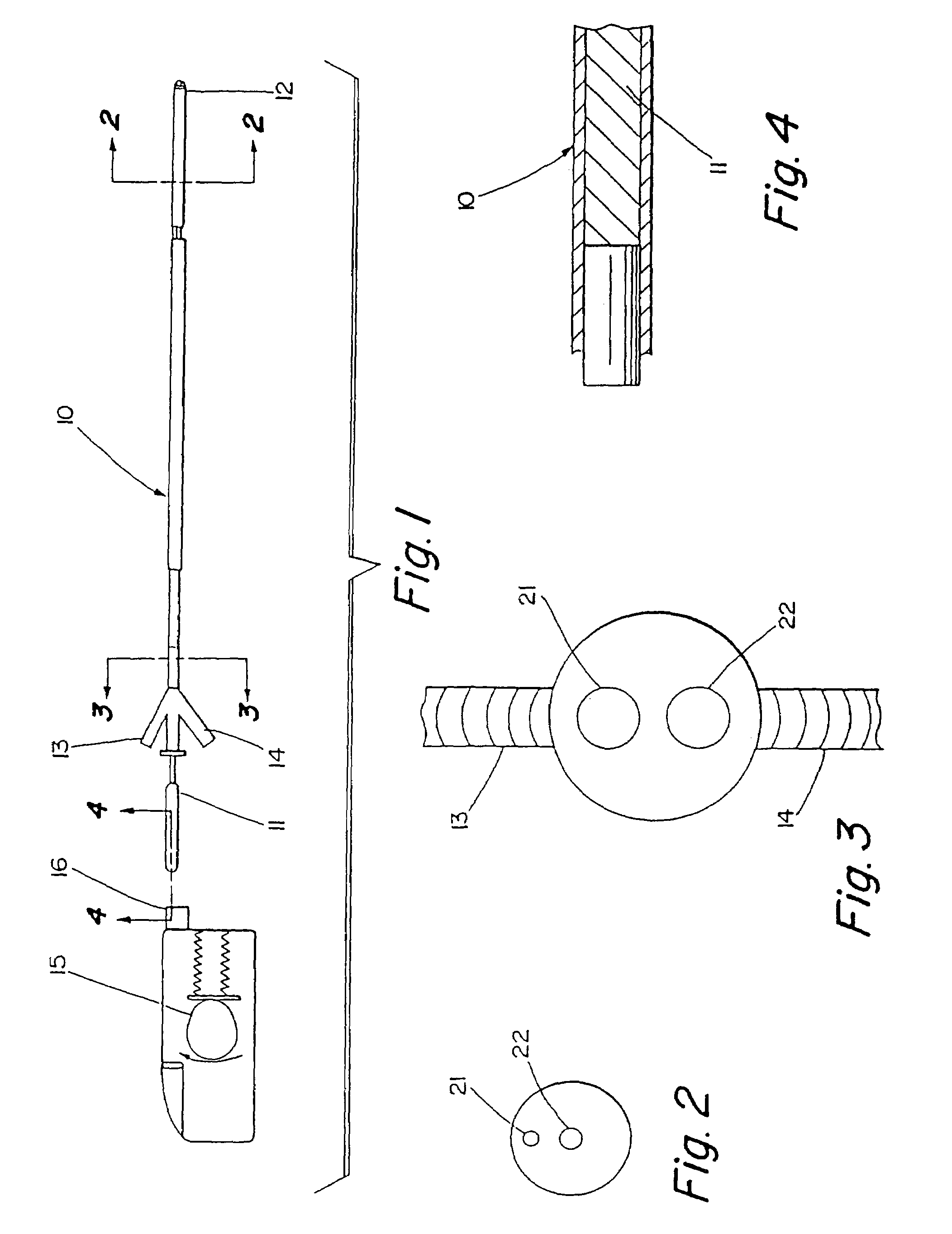
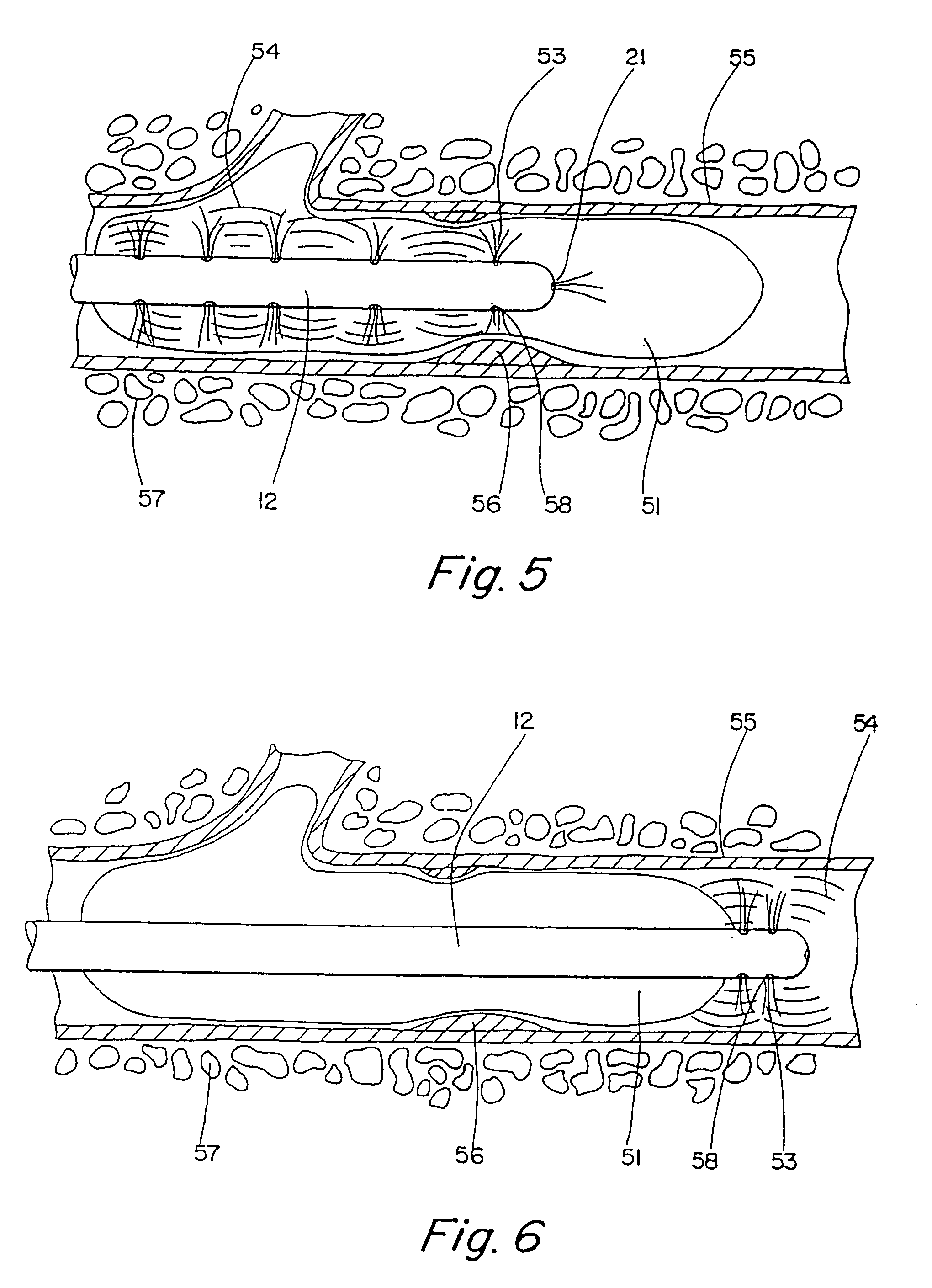
A catheter suitable for dissolving blockages in tubular tissue provides a combination of low frequency (1–100 Hz) vibratory motion and injection of a lysing agent. The tubular tissue may be veins, arteries, ducts, intestines, or any other blocked body lumen. For vascular thrombi, the catheter may induce a vibrating, stirring action in and around the thrombus in combination with dispensing of a thrombolytic agent, such as urokinase, into the thrombus. An inflatable or expandable member may be provided near a distal tip of the catheter to prevent release of dislodged thrombus.

Description

CROSS-REFERENCES TO RELATED APPLICATIONS[0001]The present application is a continuation of U.S. patent application Ser. No. 09 / 640,499 filed Aug. 16, 2000 now U.S. Pat. No. 6,508,782, which is a continuation of U.S. application Ser. No. 09 / 504,162, filed on Feb. 15, 2000 now U.S. Pat. No. 6,547,754, which is a continuation of U.S. application Ser. No. 09 / 005,217, filed on Jan. 9, 1998, now U.S. Pat. No. 6,287,271, which was a continuation-in-part of application Ser. No. 08 / 483,071, filed on Jun. 7, 1995, now U.S. Pat. No. 5,713,848, which was a continuation-in-part of application Ser. No. 08 / 320,184, filed on Oct. 7, 1994, now U.S. Pat. No. 5,498,236, which was a continuation of application Ser. No. 08 / 065,470, filed on May 19, 1993, now U.S. Pat. No. 5,380,273, which was a continuation-in-part of application Ser. No. 07 / 885,665, filed on May 19, 1992, now abandoned, the full disclosures of which are incorporated herein by reference.BACKGROUND OF THE INVENTION[0002]1. Field of the I...

Claims


Application Information

Patent Timeline
Patent Type & Authority Patents(United States)
IPC IPC(8): A61B17/22A61M29/02A61B19/00A61F2/06A61F2/84
CPCA61B17/22A61B17/22012A61M25/104A61B19/54A61B2017/22067A61B2017/22084A61F2/958A61M2025/1052A61M2025/1093A61B90/39
Inventor EVANS, MICHAELDUBRUL, WILL R.
Owner TYCO HEALTHCARE GRP LP
Learn More