System for thermal and catalytic cracking of crude oil

a crude oil thermal cracking and catalytic technology, applied in separation processes, physical/chemical process catalysts, liquid degasification, etc., to achieve the effect of low effect on catalytic efficiency and efficient and intensive oil product processing

Inactive Publication Date: 2005-08-30
ZHURIN VIACHESLAV V
View PDF19 Cites 11 Cited by
  • Summary
  • Abstract
  • Description
  • Claims
  • Application Information

AI Technical Summary

Benefits of technology

[0011]The system of consecutive heating and extraction of products of definite fraction composition in such devices including vortex vapor generators permits obtaining pure homogenous products of oil refining with utilization of distillation and / or both thermal and catalytic cracking thereby producing significant simplification of the system design, and substantial reducing metal content and increasing capacity.
[0089](a) A tubular furnace utilized for heating of the initial product up to temperatures corresponding to heavy fractions boiling in a range of 300-500 C. For obtaining of more narrow fractional composition of catalytic products, a furnace and heat exchangers provide heating of the initial product in sufficiently narrow range of different temperatures distinguished by intensity of heat exchange inside the furnace. This eliminates the necessity for utilization of several furnaces for successive heating of initial components;

Problems solved by technology

In oil refining processes using catalytic cracking, the main problem is combining a liquid boiling layer with a catalyst layer in the so-called catalytic cracking reactors with a pseudo-liquefied layer of a catalyst.

Method used


Image

  • System for thermal and catalytic cracking of crude oil
  • System for thermal and catalytic cracking of crude oil
  • System for thermal and catalytic cracking of crude oil

Examples


Embodiment Construction

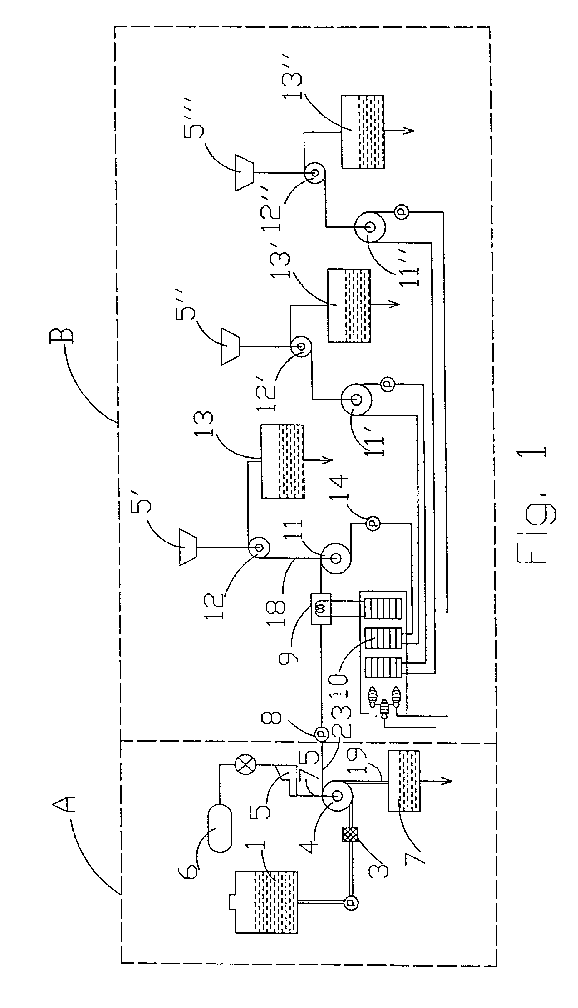
Scheme of Technological Process for Oil Distillation and Thermal Cracking Separation

[0108]In FIG. 1 consecutive technological process stages for preliminary refinement of crude oil and fraction distillation during thermal separation are illustrated.

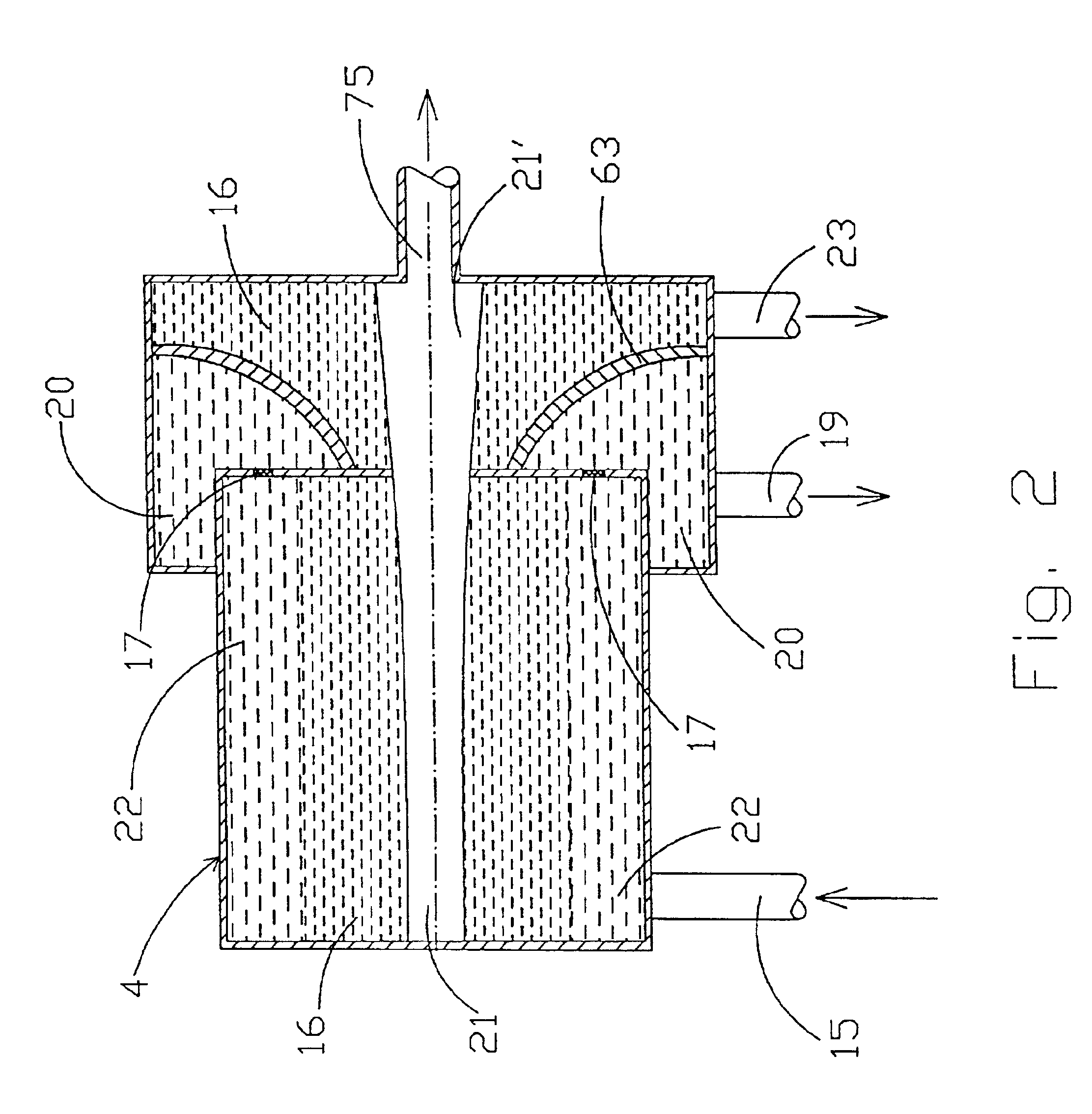
[0109]There are two units in this arrangement. Unit A contains devices utilized for primary purification of a crude oil from water and admixtures. A non-purified raw oil, i.e., a crude oil from a reservoir 1, or directly from an oil pipeline by a pump 2 is supplied through a coarse filter of mechanical admixtures 3 into a vortex separator 4 where separation of oil from gas admixtures and water takes place. Satellite gases H2, N2, O2, H2S and others are separated from water and oil mixture and directed through a pipeline 75 into a compressor 5 for pumping into containers 6. Water separated from oil in the vortex separator 4 is directed through a pipeline 19 into a reservoir 7.

[0110]The design of the vortex separator 4 is illustrated in FIG...


PUM

PropertyMeasurementUnit
pressureaaaaaaaaaa
pressuresaaaaaaaaaa
lengthaaaaaaaaaa

Abstract

In this invention the system and processes for organization of oil refinery from gases and heavy admixtures with a separation of purified oil for fractions obtained in the process of thermal distillation, and thermal and catalytic cracking and subsequent fine separation of products for narrow fractions are presented. The combining of vortex vapor generation processes of preliminary heated oil in the field of inertia forces of rotating liquid with condensation processes of gaseous products at reduced pressure in vortex vapor condensers with cooled walls with utilization of subsequent heating and productions of fuels with narrow fraction composition permits to obtain a high quality product. New types of vortex devices are presented: the vortex separator of oil from water and admixtures, the vortex vapor generator for production of fine vapor fractions, the vortex vapor condenser for condensation of vaporized fractions, the vortex vapor generator in a catalyst layer moving in a boiling layer, which is a catalytic reactor with a regulated contact time between a catalyst and a boiling layer. A two-zone combustion furnace helps to decrease energy spending, improves combustion completeness.

Description

CROSS-REFERENCE TO RELATED APPLICATION[0001]This application is based upon, and claims the benefit of, our Provisional Application No. 60 / 174,687, filed Jan. 6, 2000.BACKGROUND OF THE INVENTION[0002]1. Field of the Invention[0003]The present invention relates generally to the field of separation technologies. In particular, this invention relates to separation of liquids from liquids and separation of gases from liquids. Even more particularly, this invention relates to refining of hydrocarbon liquids into fractions by distillation and / or thermal and catalytic cracking.[0004]2. Description of the Prior Art[0005]Prior systems for crude oil refining depend on gravitational fields for separation of oil from water and heavy admixtures from water-oil emulsion. Oil refining for fractions is carried out in the rectification columns (sometime called distillation towers), in which the separation efficiency of oil for fractions is low due to an insufficient value of the vapor pressure gradien...

Claims


Application Information

Patent Timeline
Patent Type & Authority Patents(United States)
IPC IPC(8): B01D5/00B01D17/00B01D19/00C10G51/00C10G9/00C10G51/04C10G11/00
CPCB01D5/0021B01D17/00B01D17/005B01D19/0057C10G9/00C10G11/00C10G51/04B01D17/0217
Inventor ZHURIN, VIACHESLAV V.TIKHONOV, VICTOR B.
Owner ZHURIN VIACHESLAV V
Why Eureka
Try Eureka