Particle therapy system

a particle therapy and system technology, applied in the field of particle therapy system, can solve the problems of troublesome operation, unavoidable deviation of the direction of the beam axis, and large labor and time required to carry out the operation of correcting the beam orbi

Inactive Publication Date: 2005-08-30
HITACHI LTD
View PDF12 Cites 195 Cited by
  • Summary
  • Abstract
  • Description
  • Claims
  • Application Information

AI Technical Summary

Benefits of technology

[0016](1) To achieve the above object, the present invention provides a particle therapy system comprising an accelerator for accelerating a charged-particle beam to a set level of energy, and a rotating irradiation facility for irradiating the charged-particle beam extracted from the accelerator, the irradiation facility comprising a first beam transport unit for transporting the charged-particle beam extracted from the accelerator, and an irradiation field forming unit for forming an irradiation field of the charged-particle beam transported by the first beam transport unit, wherein the particle therapy system further comprises a first beam position detecting unit arranged along an orbit of the charged-particle beam downstream of a most downstream one of magnets provided in the first beam transport unit, and detecting a position at which the charged-particle beam passes; a second beam position detecting unit arranged along the orbit of the charged-particle beam downstream of the first beam position detecting unit, and detecting a position at which the charged-particle beam passes; a first steering magnet and a second steering magnet both provided in the first beam transport unit upstream of the first beam position detecting unit; a first displacement amount computing unit for determining respective first displacement amounts, by which the position of the charged-particle beam is to be displaced by the first and second steering magnets, in accordance with detected signals outputted from the first and second beam position detecting units; and a first control unit for controlling respective excitation currents of the first and second steering magnets in accordance with the respective first displacement amounts.

Problems solved by technology

In practice, however, it is unavoidable that the direction of the beam axis is slightly deviated because of shape or dimension tolerances of the components of the transport means and layout or assembly errors (referred to also as “alignment errors” hereinafter).
Thus, in the conventional therapy system, because the beam orbit has been corrected on a trial-and-error basis while manually changing the kick amount of each steering magnet, a lot of labor and time have been required to carry out the operation of correcting the beam orbit.
Hence, the operation of correcting the beam orbit must be repeated on a trial-and-error basis whenever the rotational angle of the rotating irradiator (rotating irradiation facility) is changed, thus resulting in a very troublesome operation.

Method used


Image

  • Particle therapy system
  • Particle therapy system
  • Particle therapy system

Examples


first embodiment

[0046]the present invention will be described with reference to FIGS. 1 to 5.

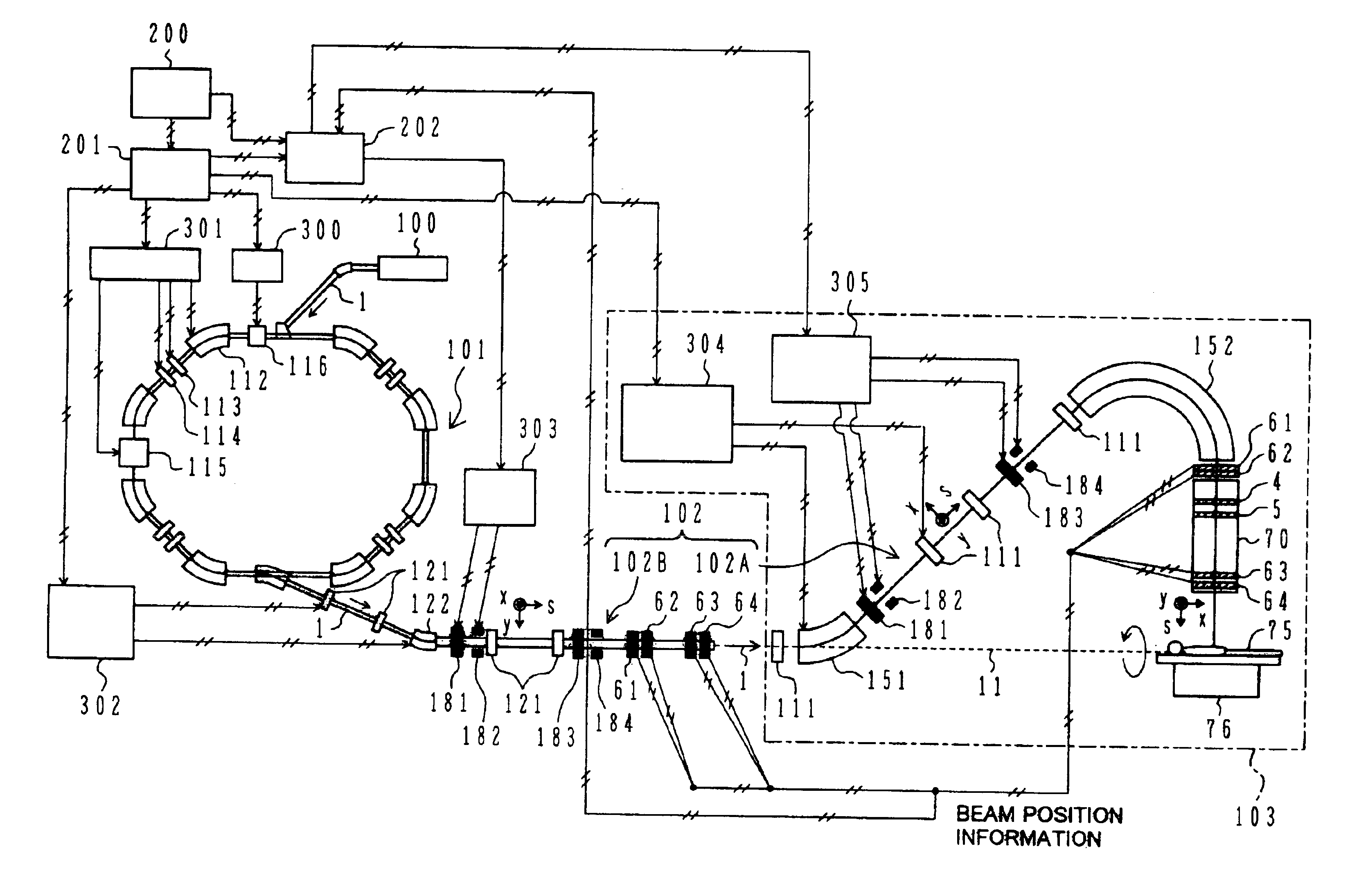
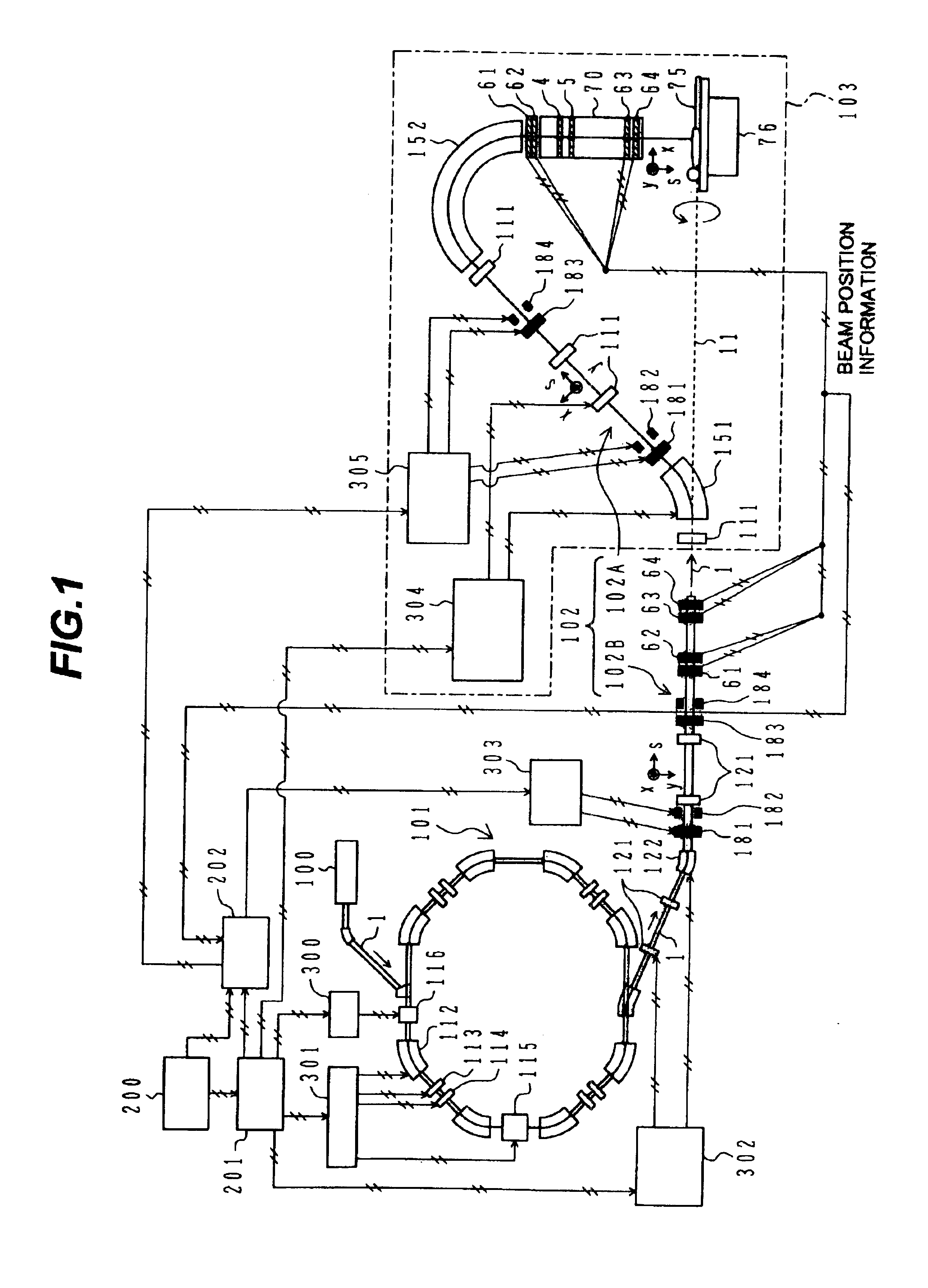
[0047]FIG. 1 is a system block diagram showing the overall construction of a particle therapy system according to a first embodiment of the present invention. For easier understanding of the overall construction, FIG. 1 includes, on the same drawing sheet, a side view showing the construction on the side of a rotating irradiation facility 103 (described later) and a plan view showing the construction of the remaining section on the side of a main accelerator 101 (described later). Correspondingly, to avoid misunderstanding, FIG. 1 also includes an x-coordinate axis representing a direction vertically upward from the drawing sheet, an s-coordinate axis representing a direction of beam propagation, and a y-coordinate in a direction perpendicular to both the x- and s-axes. Further, to avoid complication of the drawing, a flow of part of signals is not shown.

[0048]In FIG. 1, a particle therapy system of this em...

second embodiment

[0126]the present invention will be described with reference to FIG. 6. In this second embodiment, the beam orbit correction can be further simplified by utilizing a phase difference of betatron oscillation.

[0127]FIG. 6 is a system block diagram showing the overall construction of a particle therapy system according to this second embodiment. To avoid complication of the drawing, a flow of part of signals is not shown as in FIG. 1.

[0128]A description is now made of the principles of this second embodiment, which differ from those of the above first embodiment.

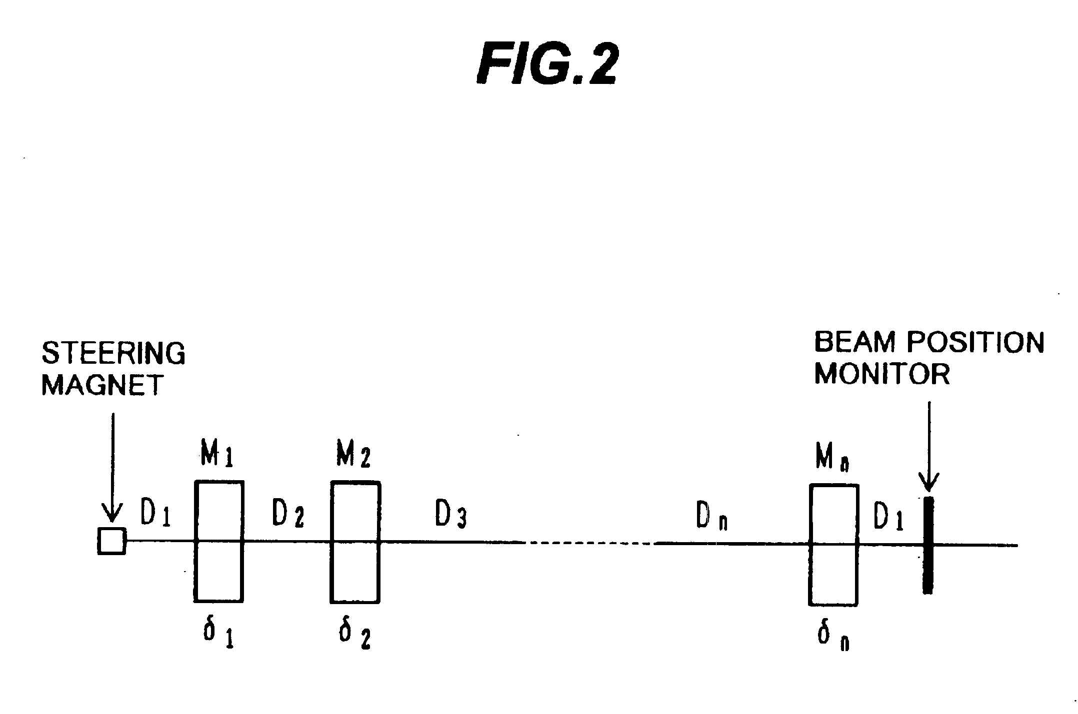
[0129]Generally, as stated in, e.g., OHO′ 94 “Fundamentals of Beam Dynamics in Electron Storage Ring”, page I-44, a transfer matrix between two A and B points in a particle design orbit can be expressed as given below using Twiss Parameters at each point: M=(βbβa⁢(cos⁢ ⁢Δ⁢ ⁢ψ+αa⁢sin⁢ ⁢Δ⁢ ⁢ψ)βa⁢βb⁢sin⁢ ⁢Δ⁢ ⁢ψ-1+αa⁢αbβa⁢βb⁢sin⁢ ⁢Δ⁢ ⁢ψ+αa-αbβa⁢βb⁢cos⁢ ⁢Δ⁢ ⁢ψβaβb⁢(cos⁢ ⁢Δ⁢ ⁢ψ-αb⁢sin⁢ ⁢Δ⁢ ⁢ψ))(3⁢-⁢1)

[0130]In the above formula (3-1),...

fourth embodiment

[0140]the present invention will be described with reference to FIG. 8. In this fourth embodiment, the present invention is applied to only the side of the rotating gantry.

[0141]FIG. 8 is a system block diagram showing the overall construction of a particle therapy system according to this fourth embodiment. To avoid complication of the drawing, a flow of part of signals is not shown as in FIGS. 1, 6 and 7.

[0142]As shown in FIG. 8, the particle therapy system of this embodiment is constructed by omitting the second steering magnets 183, 184 provided in the second beam transport system 102B from the construction of the first embodiment.

[0143]Stated otherwise, in this fourth embodiment, the orbit correction of the beam 1 is performed by correcting the beam orbit in the second beam transport system 102B with the manual adjustment on a trial-and-error basis as conventional, and by applying the present invention to only the rotating gantry side and correcting the beam orbit based on the ...


PUM


Abstract

A particle therapy system is provided which can simply and quickly correct a beam orbit. In a particle therapy system provided with an irradiation facility comprising a first beam transport system for receiving a beam and transporting the beam to the patient side, and an irradiation nozzle for forming an irradiation field of the beam, the particle therapy system comprises first beam position monitors for detecting a position upstream of the irradiation nozzle at which the beam passes, second beam position monitors for detecting a position downstream of the irradiation nozzle at which the charged-particle beam passes, and first and second steering magnets. Correction bending amounts for causing the beam to be coincident with a predetermined orbit after the correction are determined in accordance with detected results from the first and second beam position monitors, and first and second steering magnets are excited under control so that the determined correction bending amounts are obtained.

Description

CROSS REFERENCE TO RELATED APPLICATIONS[0001]The present application is a continuation of U.S. application Ser. No. 10 / 395,144, filed on Mar. 25, 2003, now U.S. Pat. No. 6,774,383, the disclosure of which is herewith incorporated by reference in its entirety.BACKGROUND OF THE INVENTION[0002]1. Field of the Invention[0003]The present invention relates to a particle therapy system for treating diseases, such as cancer and tumor, by using a charged-particle beam.[0004]2. Description of the Related Art[0005]In a therapy system for treating diseases, such as cancer and tumor, by irradiating protons or heavy ions, as charged particles, to a diseased area of a patient, a charged-particle beam accelerated by an accelerator, e.g., a synchrotron, is incident upon a transport means provided in a rotating (or stationary) irradiation facility, and is then introduced to an irradiation field forming apparatus. After shaping an irradiation field in match with the shape of the diseased area by the i...

Claims


Application Information

Patent Timeline
Patent Type & Authority Patents(United States)
IPC IPC(8): G21K1/093G21K1/00G21K5/04H05H7/04H05H7/00A61N5/10H05H13/04
CPCA61N5/1048G21K1/093G21K5/04H05H7/04A61N5/1065A61N2005/1087
Inventor NORIMINE, TETSUROUMEZAWA, MASUMIHIRAMOTO, KAZUO
Owner HITACHI LTD
Why Eureka
Try Eureka