Synchronization of machine and load characteristics

Inactive Publication Date: 2005-08-30
NIDEC SR DRIVES
View PDF15 Cites 10 Cited by
  • Summary
  • Abstract
  • Description
  • Claims
  • Application Information

AI Technical Summary

Benefits of technology

[0013]According to another embodiment of the invention there is provided a method of driving a load, having a cyclically variable input requirement and a generally repeatable rest position, by an electric motor having a cyclically variable output, the method comprising: coupling the motor with respect to the load such that the cyclically variable output is rising at start-up to boost the acceleration of the load from the rest position.
[0014]Embodiments of the invention, rather than seeking to suppress the output ripple of an electrical machine, such as a switched reluctance machine, provide a way of capitalizing on it by harnessing it when the machine is coupled to a load which also has input (load) ripple or a starting requirement involving rapid acceleration. The peak load dema

Problems solved by technology

By contrast, it is known that the single-phase induction motor has a very high torque ripple (since the torque is produced by a pulsating, rather than a rotating field), so it would not be considered a good choice for applications where, say, the load had a low inertia and was sensitive to torque ripple.
One of the criticisms which is frequently levelled at the switched reluctance machine is that it has inherently high torque ripple which can only be suppres

Method used


Image

  • Synchronization of machine and load characteristics
  • Synchronization of machine and load characteristics
  • Synchronization of machine and load characteristics

Examples


Embodiment Construction

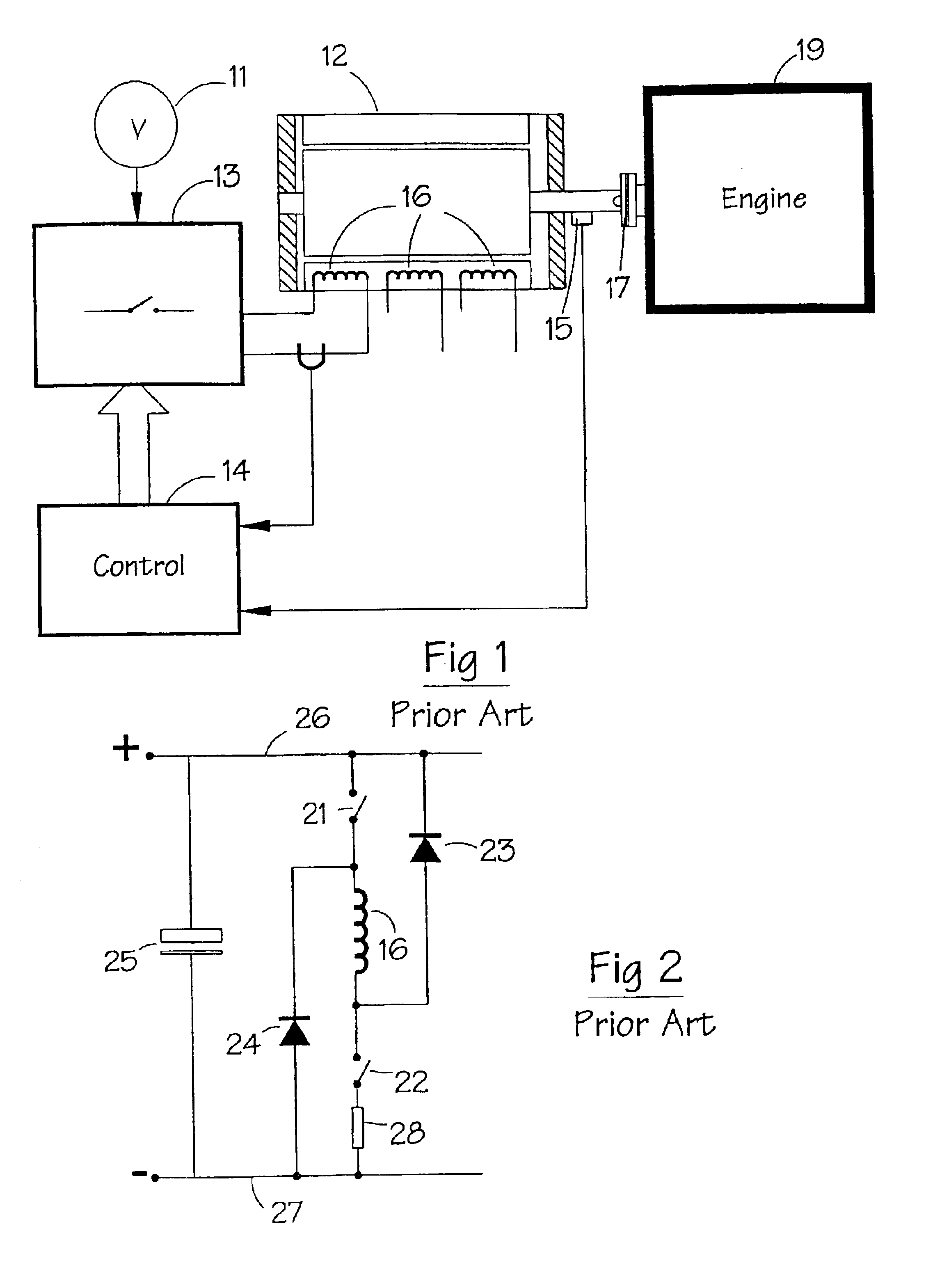
[0032]For the sake of example, the following description of the principles of the invention is based on a switched reluctance machine and an internal combustion (i.e.) engine, constituting a load. While the invention can be applied with particular benefit to this combination, it should be understood that the invention can be applied to other types of electrical machine and other loads. FIG. 1 shows a typical switched reluctance drive in schematic form, where the switched reluctance machine 12 is connected to the i.e. engine 19 by a coupling 17. The input DC power supply 11 can be either a battery or rectified and filtered AC mains. The DC voltage provided by the power supply 11 is switched across the phase windings 16 of the motor 12 by a power converter 13 under the control of the electronic control unit 14. The switching must be correctly synchronized to the angle of rotation of the rotor for proper operation of the drive, and a rotor position detector 15 is typically employed to ...


PUM


Abstract

An electrical machine is coupled to a load which has a torque profile which varies with angle. The machine is coupled so that the torque ripple of the machine is synchronized with the torque ripple of the load in such a manner as to provide an efficient drive system which can start at any angular position. This allows the size of the electrical machine to be reduced to a point where its average torque may be below the peak requirement of the load.

Description

CROSS REFERENCE TO RELATED APPLICATION[0001]The subject matter of this application is related to the subject matter of British Application No. 0112673.9, filed May 24, 2001, priority to which is claimed under 35 U.S.C. § 119 and which is incorporated herein by reference.BACKGROUND OF THE INVENTION[0002]1. Field of the Invention[0003]The present invention generally relates to a system and method of driving a load having a cyclically variable input requirement. More particularly, but not exclusively, the invention relates to the synchronization of the output characteristic of an electrical machine with the load characteristic of the apparatus to which it is coupled.[0004]2. Description of Related Art[0005]Many types of rotating electrical machines are known for coupling to mechanical equipment, either to act as motors and thus drive the equipment by supplying mechanical power to it, or to act as generators and thus be driven by the equipment by drawing mechanical power from it. Genera...

Claims


Application Information

Patent Timeline
IPC IPC(8): H02K7/18H02K7/00H02P1/00
CPCH02K7/006H02K7/1815H02P25/098H02P1/00
Inventor ELLIOTT, CHARLES RICHARDMCCLELLAND, MICHAEL LEO
Owner NIDEC SR DRIVES
Why Eureka
Try Eureka