Phase discriminator with a phase compensation circuit

a phase compensation circuit and phase discriminator technology, applied in phase-modulated carrier systems, amplitude demodulation, transmission monitoring, etc., can solve the problems of no mechanism to correct timing errors, impossible perfect timing recovery, and noise and interference to corrupt the clock information carried by the pilot ton

Inactive Publication Date: 2005-08-30
SILICON INTEGRATED SYSTEMS
View PDF6 Cites 4 Cited by
  • Summary
  • Abstract
  • Description
  • Claims
  • Application Information

AI Technical Summary

Benefits of technology

[0008]This invention has been made to overcome the above mentioned drawbacks of conventional timing recovery circuits using a DPLL. The primary object of this invention is to provide a simple phase compensation circuit for a phase discriminator to compensate for timing drift and error. The simple circuit generates a phase compensation value to be added to the uncorrected discriminator output and forces the received pilot tone signal to be close to the 4-QAM signal on the 2-D signal plane.
[0009]Accordingly, the phase discriminator of this invention comprises a conventional phase discriminator in parallel with a phase compensation circuit. Based on the quadrant in which a pilot tone is located in the 2-D signal plane, a phase correction term can be computed in the phase compensation circuit. A weighting factor defined and derived from the pilot tone is also calculated to adjust relative weighting between the phase correction term and the uncorrected output of the phase discriminator to form the phase corrected output. The phase discriminator of this invention provides a timing recovery circuit without a complicated phase calculation and compensation circuit to overcome the timing drift problem. Normalization or other numerical operation is also not necessary in the circuit and, thus, it greatly reduces the required hardware.

Problems solved by technology

In a practical implementation, however, noises and interference corrupt the clock information carried by the pilot tone.
Thus, perfect timing recovery is impossible.
In addition, inter-frame interference occurs and no mechanism can correct the timing error.
However, quantization error due to fixed point numerical operations results in slight phase rotation.
After a period of time, the small phase difference accumulates gradually and results in synchronization failure between ATU-C and ATU-R.
These approaches add considerable hardware cost because both normalization and arc-tangent require relatively complicated numerical operations as compared with other parts in a DPLL circuit.

Method used


Image

  • Phase discriminator with a phase compensation circuit
  • Phase discriminator with a phase compensation circuit
  • Phase discriminator with a phase compensation circuit

Examples


Embodiment Construction

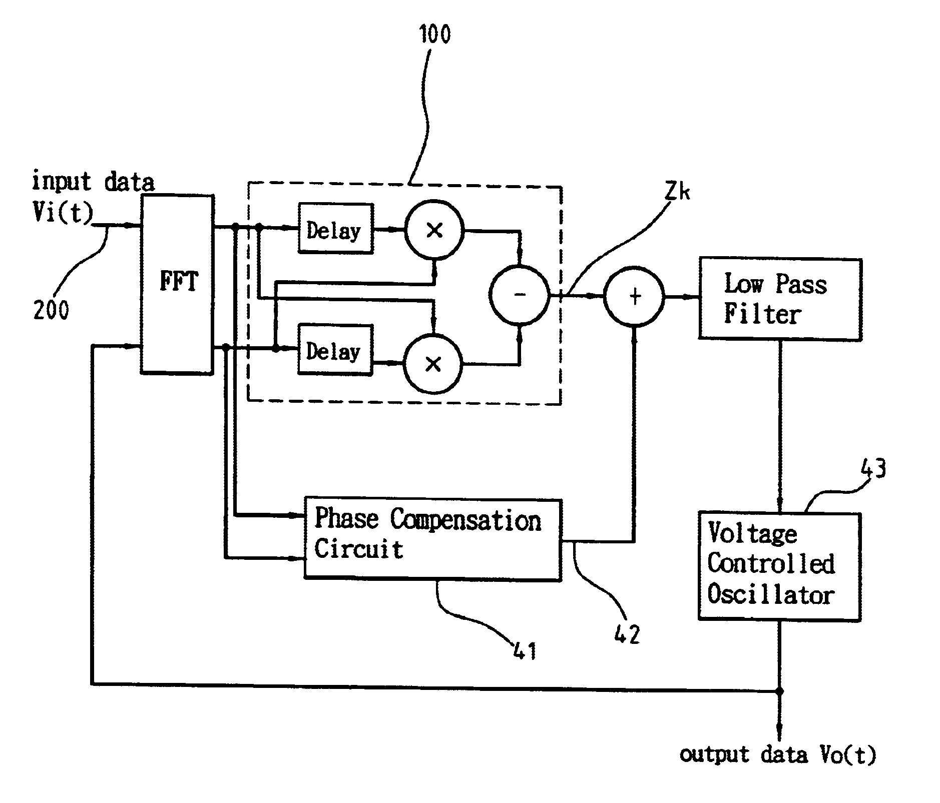
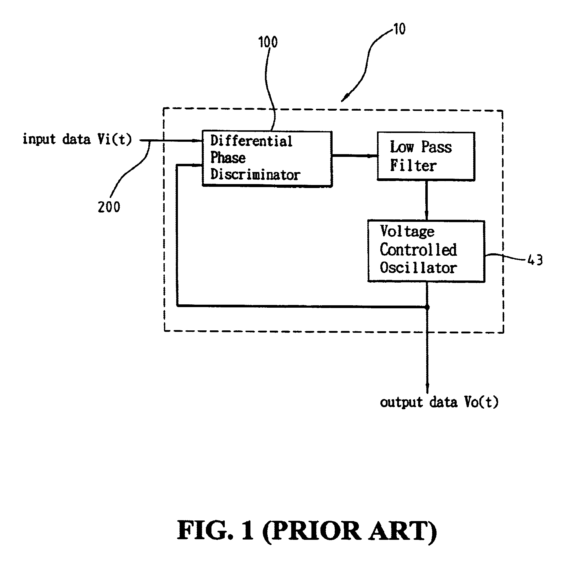
[0015]In the conventional demodulation technology, the received signal may suffer from timing drift because of the frequency difference between the remote oscillator and the local oscillator. This timing drift makes it very difficult for coherent demodulation. By means of generating a phase compensation value to compensate for the deficiency of the conventional differential phase discriminator circuit, this invention adjusts the frequency of the local oscillator to achieve the goal of coherent modulation.

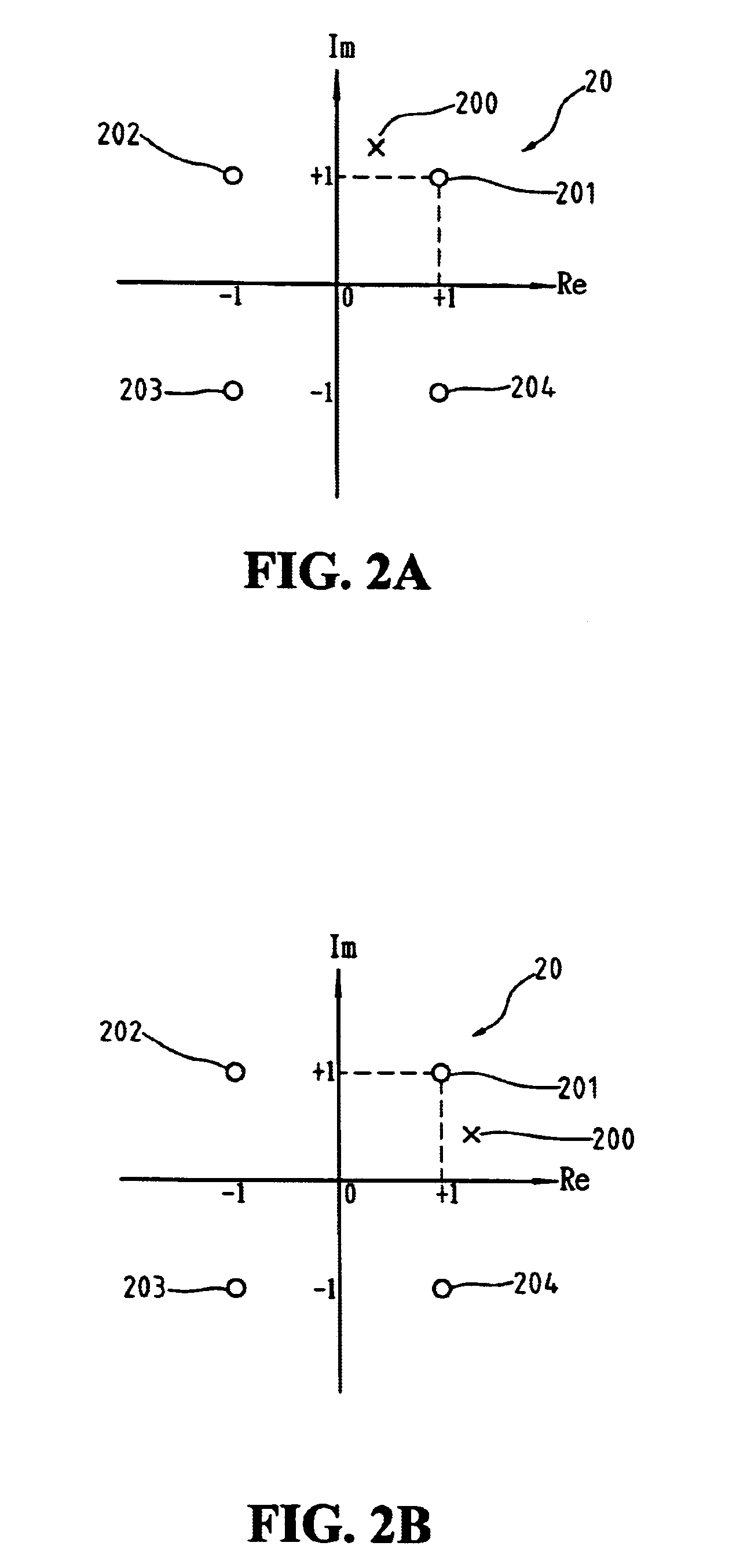
[0016]With reference to FIG. 3, the phase compensation value of this invention is defined as the product of a phase correction term Vk and a weighting factor Wk. The phase correction term Vk is defined as Vk=abs(Yk)−abs(Xk) for a pilot tone sample located at the first or the third quadrant on the 2-D signal plane, and Vk=abs(Xk)−abs(Yk) for a pilot tone sample located at the second or the fourth quadrant on the 2-D signal plane, where abs(x) denotes the absolute value of the enclose...


PUM


Abstract

A differential phase discriminator includes a phase compensation circuit to compensate for timing drift and error for recovering timing information in a digital phase lock loop. The differential phase discriminator uses a differential phase detector to compute the phase difference of two consecutive frequency domain signal samples. The phase compensation circuit determines a phase correction term by computing the difference between the absolute values of the real and imaginary parts of a frequency domain signal sample. A weighting factor is computed by adjusting the sum of the absolute values of the real and imaginary parts of the frequency domain signal sample with a ratio adjustment factor. A phase compensation value is then computed by multiplying the phase correction term by the weighting factor. The phase compensation value is added to the uncorrected output of the differential phase detector.

Description

FIELD OF THE INVENTION[0001]The present invention generally relates to a timing recovery circuit in an asymmetric digital subscriber line (ADSL) system, and more specifically to a phase discriminator having a phase compensation circuit for a digital-phase-lock-loop (DPLL) to locally recover the clock frequency information delivered from a central office.BACKGROUND OF THE INVENTION[0002]In ADSL standards such as T1E1.4 and G.DMT, the 4-QAM modulation scheme is adopted to modulate a pilot tone for carrying timing information from a central office (ATU-C) site to a remote terminal (ATU-R) site, or vice versa. In order to synchronize the ATU-R with ATU-C, for example, ATU-R should lock the carrier's frequency and / or phase in the pilot tone.[0003]A simple approach for an ATU-R site to recovering the clock frequency information delivered by an ATU-C site uses a DPLL with a discriminator as the phase detector to find the phase difference of two consecutive symbols without the need of a com...

Claims


Application Information

Patent Timeline
Patent Type & Authority Patents(United States)
IPC IPC(8): H04L27/38H04L27/00H03L7/085
CPCH03L7/085H04L27/3827H04L2027/003H04L2027/0057H04L2027/0067
Inventor TZOU, CHING-KAELIN, YUNG CHING
Owner SILICON INTEGRATED SYSTEMS
Why Eureka
Try Eureka