
Heat treatment apparatus with temperature control system

a technology of temperature control system and heat treatment apparatus, which is applied in the direction of lighting and heating apparatus, furnace components, furnace types, etc., can solve the problems of reducing the heat up rate, affecting the heat transfer speed of the furnace body, and affecting the heat exchange rate of the substra

Active Publication Date: 2005-09-06
ASM INTERNATIONAL
View PDF59 Cites 20 Cited by
  • Summary
  • Abstract
  • Description
  • Claims
  • Application Information

AI Technical Summary

Benefits of technology

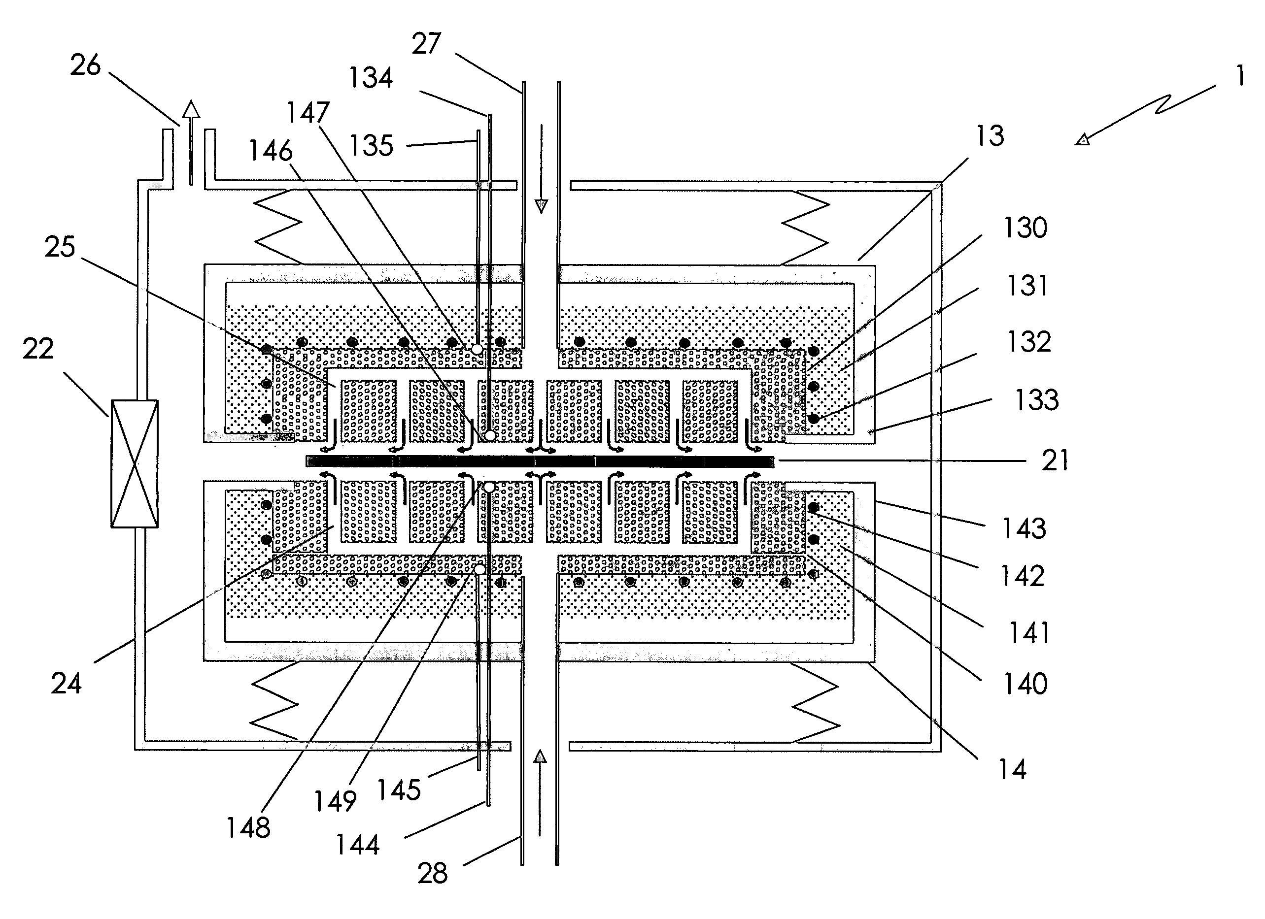
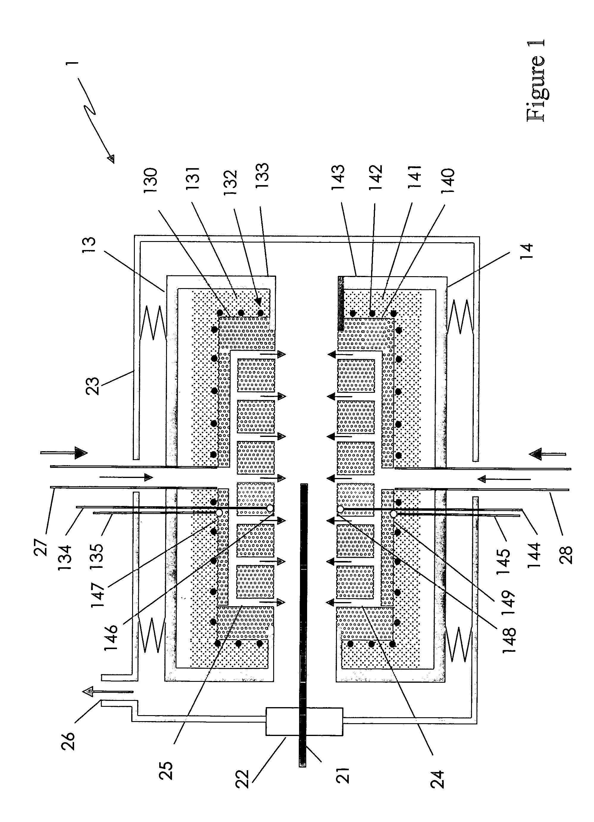
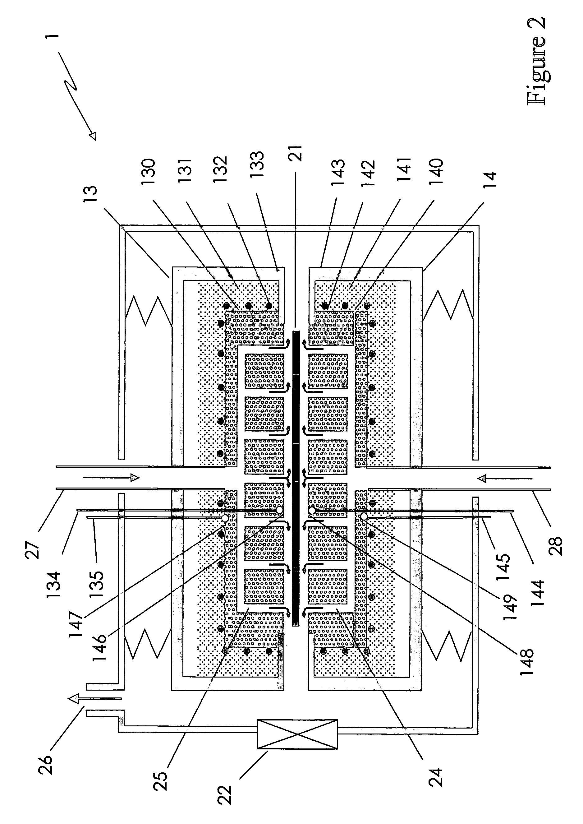
The present invention provides a heat treatment apparatus and method for controlling the temperature of a furnace body during heat treatment of semiconductor substrates. The apparatus includes a heated furnace body with a boundary surface for heating the substrates, a plurality of heating zones, and a temperature sensor for measuring the temperature of the substrate during heat treatment. A controllable heater controls the temperature of the furnace body, and a temperature regulator regulates the temperature of the boundary surface. The apparatus can also include a heat treatment cycle controller for controlling the heating of the substrates, and a substrate loading signal generator for triggering the loading of the substrates into the reactor. The method includes successively heating and unloading the substrates, and calculating a new control set-point for the heater based on the desired treatment temperature and the measured treatment temperature. The apparatus and method provide precise control over the temperature of the substrates during heat treatment, improving the quality and efficiency of semiconductor processing.

Problems solved by technology

The small gap results in a rapid heat transfer from the furnace bodies to the substrate by conduction through the gas when the substrate is processed, e.g., during a heat treatment, or exposure to elevated temperatures.
In comparison, where a transport arm transports a substrate into the reactor and then continues to support the substrate during processing, mechanical contact by support fingers of the transport arm can result in cold spots at their points of contact with the substrate during heat-up, as the support fingers represent extra thermal mass that must be heated and that locally slows down the heat-up rate during processing.
Alternatively, where a substrate is transported to the reactor and then handed off to support pins that remain in the reactor after processing, mechanical contact by support pins during processing can result in hot spots on the substrate at their contact positions, as the support pins may already have been heated by a previous process.
Although the above-described methods and apparatuses allow for a reproducible thermal treatment of a series of substrates, the timing for treating successive substrates is relatively fixed, limiting the throughput flexibility of the reactor.
In addition, even with independently controlled heating zones, the thermal recovery time may differ between the different heating zones, resulting in non-uniformities in the heat treatment temperature profile over the boundary surface.

Method used


Image

  • Heat treatment apparatus with temperature control system
  • Heat treatment apparatus with temperature control system
  • Heat treatment apparatus with temperature control system

Examples


Embodiment Construction

[0034]While the methods and apparatuses described in U.S. patent application Publication No. 2003 / 0027094 A1 allow for a reproducible heat treatment, the decrease in temperature caused by the loading of a substrate limits the processing throughput because time is needed for a furnace body to thermally recover to the desired process temperature. In particular, the time between the moment a substrate is removed from the vicinity of the furnace body and the moment when the furnace body reaches the desired temperature again often constitutes an unproductive waiting time in which the treatment apparatus is not being utilized to process a substrate. Ideally, the waiting time is not too long so as not to lose valuable throughput. This is an especially significant concern where substrates are processed one by one, since any increase or decrease in waiting time is multiplied by all the substrates that are to be processed. On the other hand, the waiting time is preferably not so short that th...


PUM

PropertyMeasurementUnit
anglesaaaaaaaaaa
anglesaaaaaaaaaa
angleaaaaaaaaaa

Abstract

A floating substrate reactor allows heat treatment of a series of semiconductor substrates, one by one. The heat treatment occurs while flowing gas suspends a substrate between two heated surfaces of the reactor. The two heated surfaces each have multiple heating zones. The heating zones are heated to desired temperature(s) and a substrate is then loaded into the reactor for heat treatment. Upon loading, the relatively cold substrate absorbs heat and cools the process chamber. A heat spike, which can be varied, is applied to the heating zones to heat the reactor to the desired temperature again. The substrate, however, is unloaded from the reactor before the temperatures of the heating zones have reached the desired temperature. After the heating zones have reached the desired temperature, the next substrate in the series of substrates is loaded into the reactor for heat treatment. The heating rate of each heating zone is independently controlled by two nested control loops in a cascade temperature control configuration, permitting differences in the heating rates of the heating zone to be accounted for, thus allowing a uniform temperature or predetermined gradient to be established across all the heating zones. The intensity of the heat spike is recalculated after the introduction of each substrate, using the heating behavior of the previous heat spike as a calculation input, to more accurately heat the heating zones to the desired temperature. The variability of the heat spike intensity from substrate to substrate also allows the throughput of the heat treatment apparatus to be varied.

Description

REFERENCE TO RELATED APPLICATIONS[0001]This application is related to U.S. application Ser. No. 10 / 151,207, METHOD AND DEVICE FOR THE HEAT TREATMENT OF SUBSTRATES, filed May 16, 2002; U.S. application Ser. No. 10 / 186,269, METHOD AND APPARATUS FOR THE TREATMENT OF SUBSTRATES, filed Jun. 27, 2002; U.S. application Ser. No. 10 / 141,517, TEMPERATURE CONTROL FOR SINGLE SUBSTRATE SEMICONDUCTOR PROCESSING REACTOR, filed May 8, 2002; U.S. application Ser. No. 10 / 410,699, TEMPERATURE CONTROL FOR SINGLE SUBSTRATE SEMICONDUCTOR PROCESSING REACTOR, filed Apr. 8, 2003; U.S. application Ser. No. 10 / 619,383, HYBRID CASCADE MODEL-BASED PREDICTIVE AND PROPORTIONAL-INTEGRAL-DERVATIVE TEMPERATURE CONTROL SYSTEM FOR VERTICAL THERMAL REACTORS, filed Jul. 14, 2003; and the patent application entitled METHOD FOR THE HEAT TREATMENT OF SUBSTRATES, filed Oct. 31, 2003, Ser. No. 10 / 700,298.BACKGROUND OF THE INVENTION[0002]1. Field of the Invention[0003]This invention relates generally to heat treatment apparat...

Claims


Application Information

Patent Timeline
Patent Type & Authority Patents(United States)
IPC IPC(8): F27B5/00F27B5/14F27D5/00H01L21/02H01L21/26H01L21/324F27B17/00F27D19/00F27D21/00H01L21/00H01L21/677
CPCF27B17/0025F27D19/00F27D21/0014H01L21/67109H01L21/67784G05D23/1931
Inventor VAN KESTEREN, TOM A.ZINGER, JAN
Owner ASM INTERNATIONAL
Learn More