
Surface acoustic wave device

Inactive Publication Date: 2005-09-06
MURATA MFG CO LTD
View PDF31 Cites 11 Cited by
  • Summary
  • Abstract
  • Description
  • Claims
  • Application Information

AI Technical Summary

Benefits of technology

[0011]In order to overcome the problems described above, preferred embodiments of the present invention provide a surface acoustic wave device including a dielectric thin film on an elastic substrate, and an IDT electrode or a reflector electrode disposed between the dielectric thin film and the elastic substrate, having strips with a reflection coefficient that is increased, thus improving the speed of the conversion and reducing the size and the insertion loss thereof.
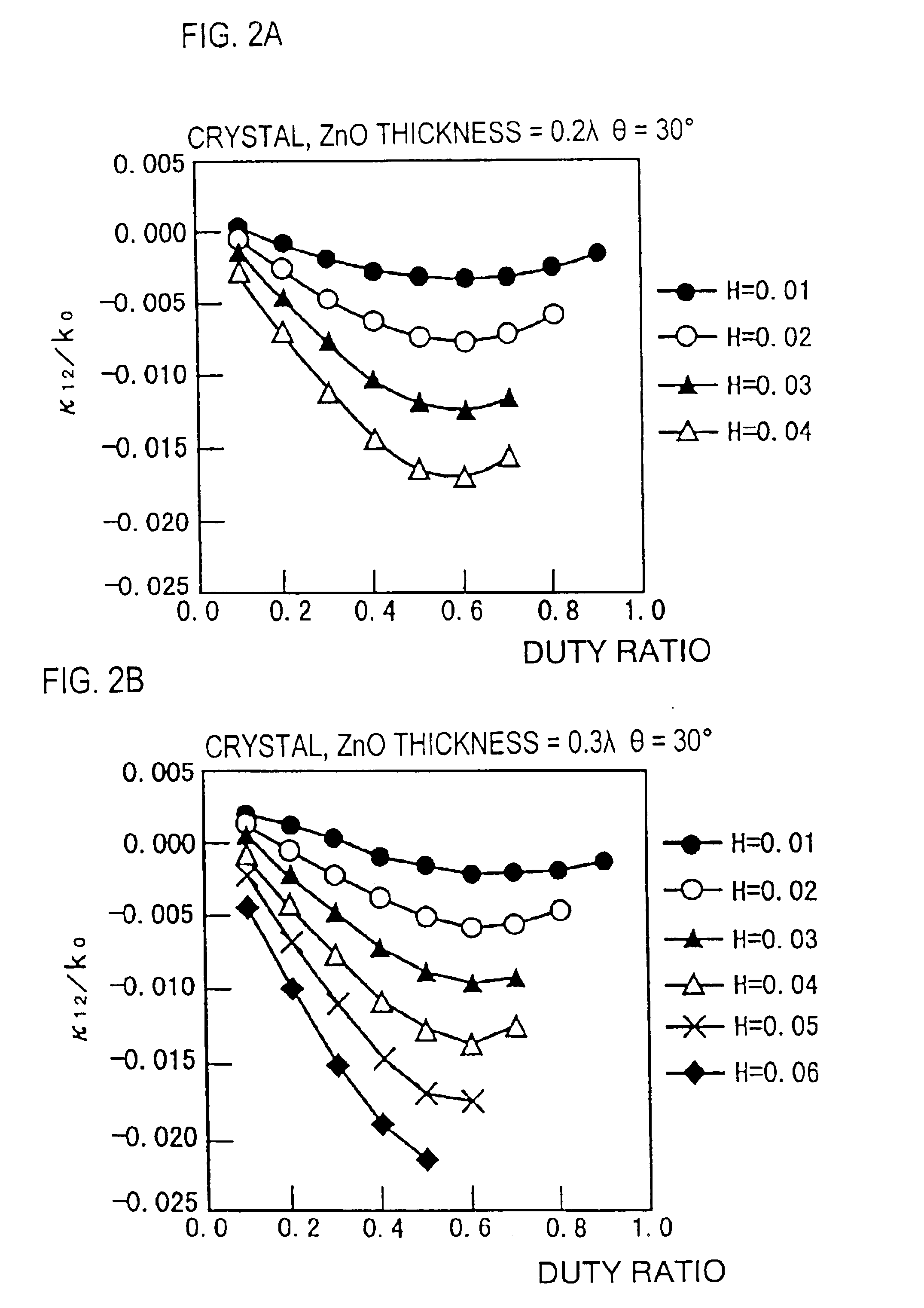
[0013]By setting the duty ratio of the strip at greater than about 0.5, the reflection coefficient of the surface acoustic wave at the strip of the IDT electrode and / or the reflector electrode is greatly increased. Therefore, the IDT electrode having a duty ratio larger than about 0.5 has an increased resonance efficiency, and results in a resonator filter having sharp filter characteristics or a resonator having a high quality factor Q.
[0014]Also, the reflector electrode having a duty ratio larger than about 0.5 increases the reflection efficiency thereof. Thus, the number of strips of the reflector electrode can be reduced, and consequently, the surface acoustic wave device can be miniaturized.
[0016]By setting the inclination angle at greater than about 30°, the reflection coefficient of the strips can be increased. Preferably, the inclination angle is greater than about 40° to further increase the reflection coefficient. Therefore, when the inclination angle is greater than about 30°, the resonance efficiency is greatly increased and thus, a resonator filter having sharp filter characteristics or a resonator having a high quality factor Q can be achieved. Also, when the inclination angle is greater than about 30°, a miniaturized reflector can be achieved.
[0019]Preferably, the thickness of the IDT electrode and / or the reflector electrode is greater than about 0.01λ, wherein λ represents the wavelength of the surface acoustic wave. Thus, the reflection coefficient of the strip is increased further.
[0020]Preferably, the density of the dielectric thin film is larger than that of the IDT electrode and / or the reflector electrode. Thus, the reflection coefficient of the strips can be effectively increased.

Problems solved by technology

The transverse structure allows strips of the IDT electrodes to reflect TTE (triple-transit echo), thus causing unwanted ripples.
Therefore, it is difficult to improve the speed of the conversion by the IDT electrode and to reduce the size and the insertion loss of the surface acoustic wave device.

Method used


Image

  • Surface acoustic wave device
  • Surface acoustic wave device
  • Surface acoustic wave device

Examples


Embodiment Construction

[0039]The present invention will be further illustrated with preferred embodiments below with reference to the drawings.

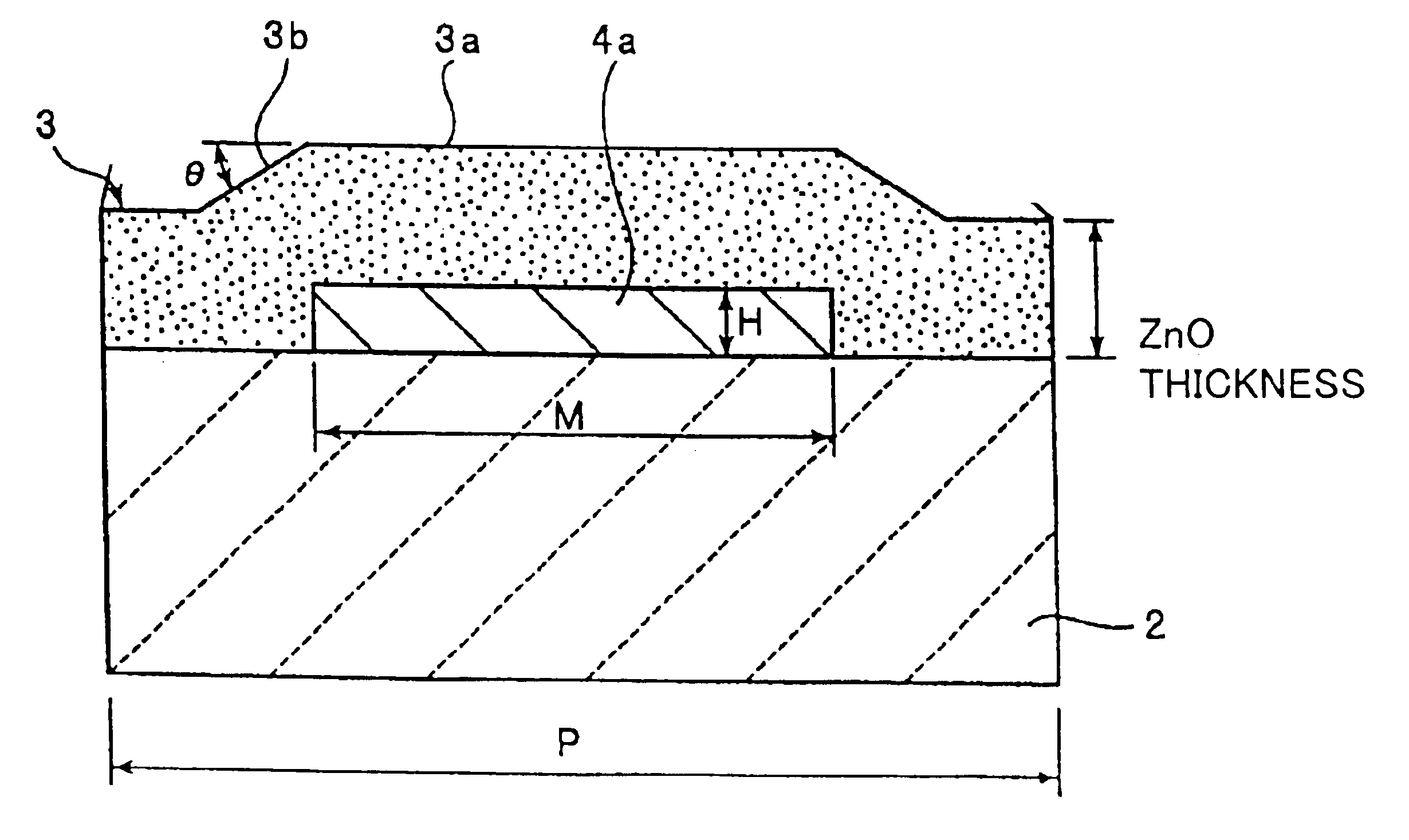
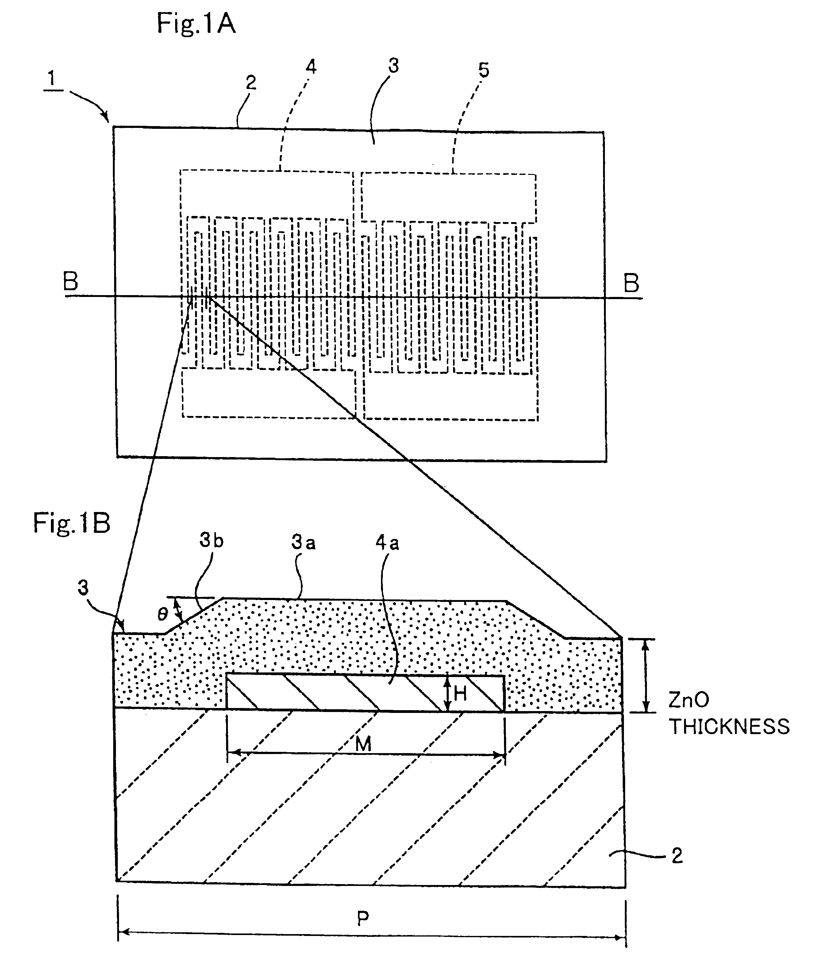
[0040]FIG. 1A is a schematic sectional view of a surface acoustic wave device according to a first preferred embodiment of the present invention and FIG. 1B is a schematic fragmentary sectional view taken along line B—B in FIG. 1A.

[0041]The surface acoustic wave device 1 of this preferred embodiment includes a ZnO thin film 3, acting as a dielectric thin film, disposed on a 27°-rotated Y-cut quartz substrate 2, for example. IDT electrodes 4 and 5 preferably made of an aluminum thin film are disposed between the quartz substrate 2 and the ZnO thin film 3.

[0042]In the surface acoustic wave device 1, the vibration of the IDT electrodes 4 and 5 generates Rayleigh waves having a surface acoustic wave velocity of about 2500 m / s to about 3000 m / s propagating in the X direction.

[0043]The ZnO thin film 3 is preferably formed on the quartz substrate 2 by a film deposition me...


PUM


Abstract

A surface acoustic wave device includes a ZnO dielectric thin film on a quartz substrate and an IDT electrode having strips between the ZnO thin film and the quartz substrate. The IDT electrode has at least one region where the strips are disposed at an interval defined by approximately a half-wavelength of the surface acoustic wave. The duty ratio of the IDT electrode is preferably more than about 0.5. Alternatively, a protrusion is formed via a slope in the region of the ZnO thin film where the IDT electrode is disposed, and the inclination angle θ of the slope is more than about 30°.

Description

BACKGROUND OF THE INVENTION[0001]1. Field of the Invention[0002]The present invention relates to surface acoustic wave devices for use as, for example, resonators and bandwidth filters, and more specifically, the present invention relates to a surface acoustic wave device including a dielectric thin film disposed on an elastic substrate and an IDT electrode or a reflector electrode disposed between the elastic substrate and the dielectric thin film.[0003]2. Description of the Related Art[0004]Surface acoustic wave devices generally used as bandwidth filters and other such filters for mobile communication equipment include at least one interdigital electrode (hereinafter referred to as an IDT electrode) including at least a pair of comb-like electrodes in contact with a piezoelectric component.[0005]A piezoelectric substrate made of various piezoelectric materials is used for the piezoelectric component. Also, surface acoustic wave devices have been introduced in which a dielectric t...

Claims


Application Information

Patent Timeline
IPC IPC(8): H03H9/145H03H9/02
CPCH03H9/14538H03H9/14552H03H9/643
Inventor KANDO, HAJIME
Owner MURATA MFG CO LTD
Learn More