Envelope functions for modulation spectroscopy

a modulation spectroscopy and envelope function technology, applied in the field ofspectroscopy, can solve the problems of inconvenient use, incurring the cost of an actuator, limited sensitivity, etc., and achieve the effect of allowing sensitive detection

Inactive Publication Date: 2005-09-06
SOUTHWEST SCI
View PDF17 Cites 30 Cited by
  • Summary
  • Abstract
  • Description
  • Claims
  • Application Information

AI Technical Summary

Benefits of technology

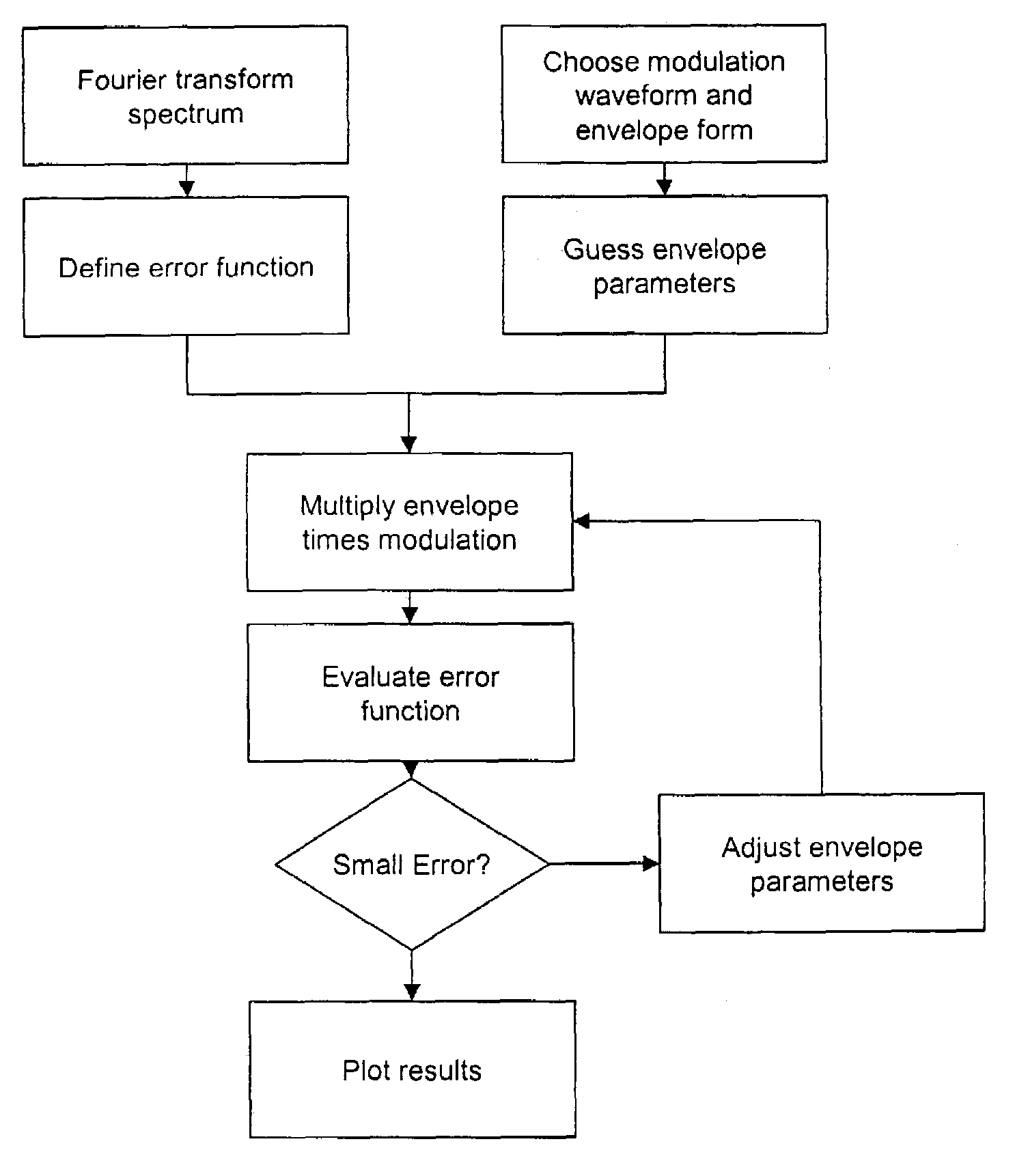
[0018]The invention is also of a method for computing a modulation waveform, comprising: specifying a target detection efficiency in a Fourier space; computing a response of a waveform that comprises a carrier wave multiplied by an envelope function; and modifying the envelope function using nonlinear optimization means to minimize a difference between the computed response and a predetermined target gain spectrum. In the preferred embodiment, the target gain spectrum comprises a signal band and a stop band.
[0019]A primary object of the present invention is to permit sensitive detection of an atomic or chemical species by modulation spectroscopy without loss of sensitivity by interference from fringes.

Problems solved by technology

In practical systems based on WMS, FMS, TBS or TTFMS, the sensitivity is limited by optical noise arising from light scattered or reflected within the optical system.
However, these approaches require mechanically changing the position of an optic, incurring the cost of an actuator.
As it is difficult to rapidly vary the pressure, this approach may not be suitable when a fast response is desired from the instrument.
These approaches have the drawback that the phases of two demodulation steps must be adjusted to achieve high sensitivity and calibration stability.
They have the further drawback that the peak modulation amplitude can be twice as large as for standard WMS or FMS.
A disadvantage of this approach is that the free spectral range of the fringe must be known, and it is not useful for eliminating more than one fringe.
However, Iguchi noted that the IIRC waveform extends to infinity, so it is impractical for a realistic instrument.
The jitter approach was found not to work when the free spectral range of the fringe was comparable to or larger than the line width of the signal.

Method used


Image

  • Envelope functions for modulation spectroscopy
  • Envelope functions for modulation spectroscopy
  • Envelope functions for modulation spectroscopy

Examples


Embodiment Construction

)

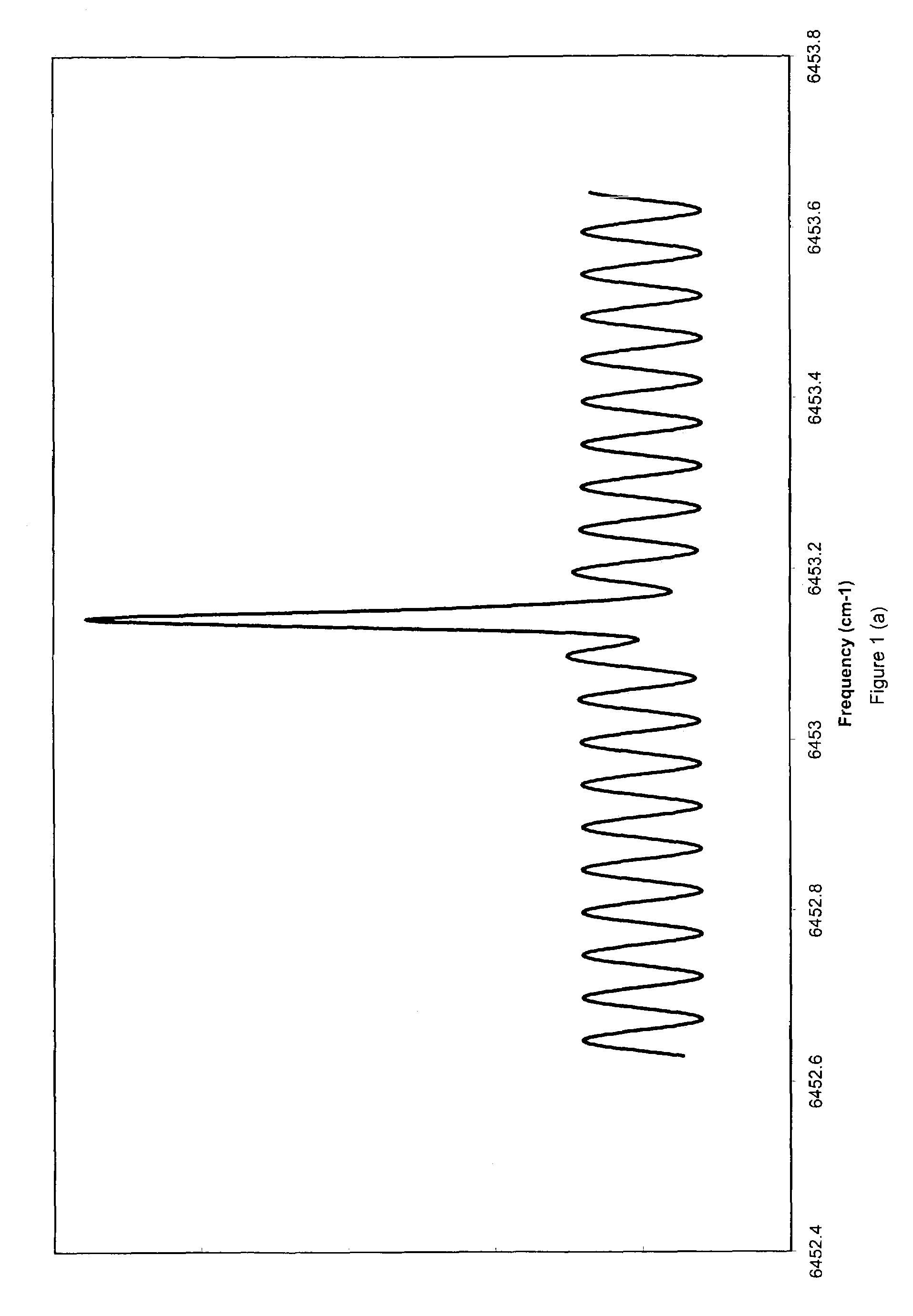
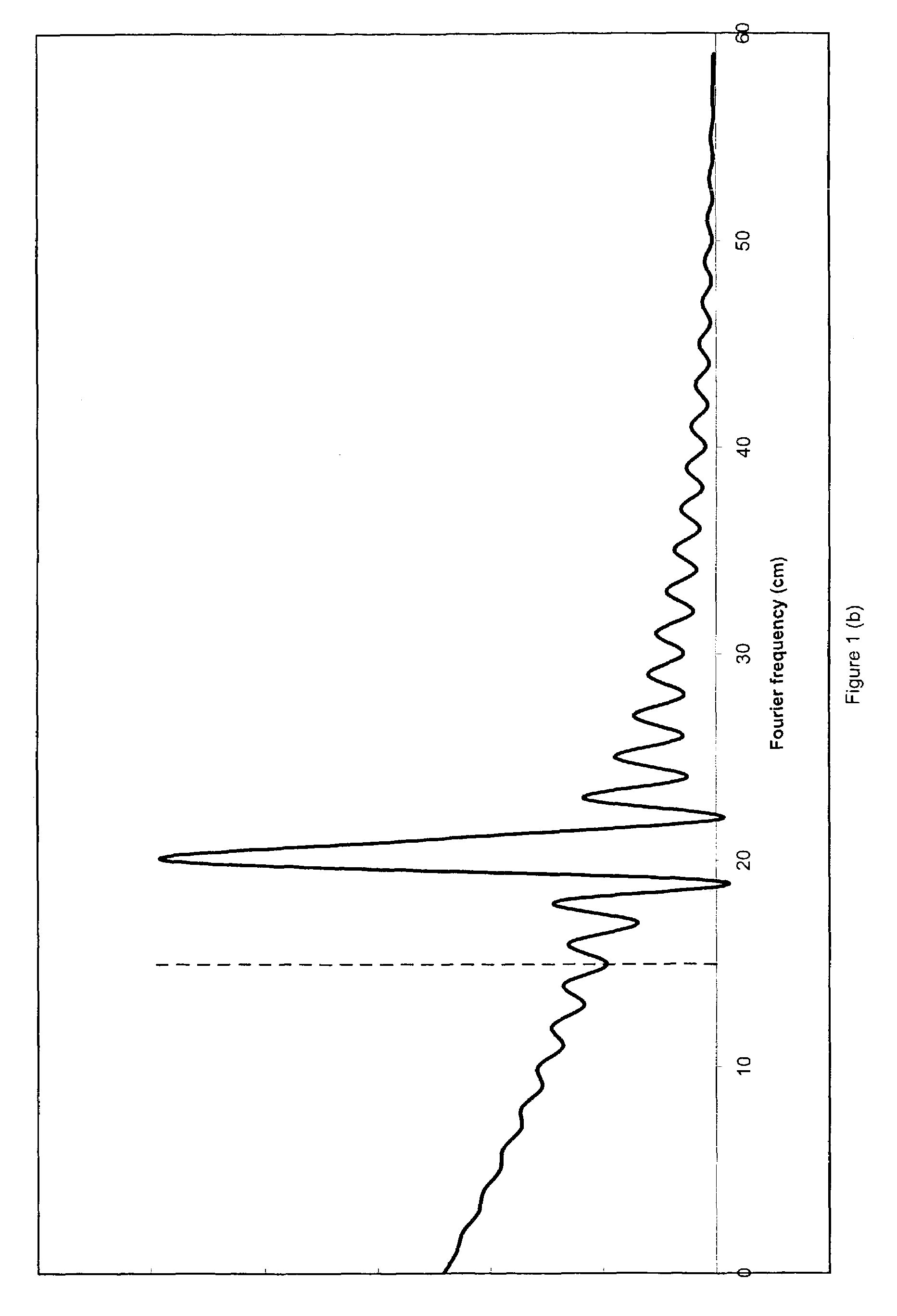
[0026]The present invention is an apparatus for and a method of preferentially detecting only those Fourier components of a spectrum that convey the most information. It employs a modulation circuit, a light source whose wavelength or frequency can be modulated, a sample path, a photodetector, and a demodulator. The modulation circuit produces a waveform, such as a sine wave or triangle wave, multiplied by an envelope function. The invention also comprises a method of modulating the light source of a spectrometer in a way to optimize the detection of certain Fourier components of a spectrum under investigation. The modulation waveform is multiplied by an adjustable envelope function. The lock-in amplifier time constant is set to be longer than the characteristic period of the envelope function. The envelope function is adjusted to give the desired performance through an optimization algorithm.

[0027]The advantages of the present invention can be obtained with any spectrometer that c...


PUM

PropertyMeasurementUnit
spectral widthaaaaaaaaaa
frequencyaaaaaaaaaa
spectrumaaaaaaaaaa

Abstract

A spectrometer and spectrometry method comprising modulating a light source with a carrier waveform multiplied by an envelope function, directing light from the light source through a sample region and to a photodetector, and demodulating current from the photodetector at a reference frequency. Also a method for computing a modulation waveform comprising specifying a target detection efficiency in a Fourier space, computing a response of a waveform that comprises a carrier wave multiplied by an envelope function, and modifying the envelope function using nonlinear optimization means to minimize a difference between the computed response and a predetermined target gain spectrum.

Description

CROSS-REFERENCE TO RELATED APPLICATIONS[0001]This application claims the benefit of the filing of U.S. Provisional Patent Application Ser. No. 60 / 355,862 filed Feb. 8, 2002, and the specification thereof is incorporated herein by reference.GOVERNMENT RIGHTS[0002]The U.S. Government has a paid-up license in this invention and the right in limited circumstances to require the patent owner to license others on reasonable terms as provided for by the terms of Contract No. 68-D-99-069 awarded by the U.S. Environmental Protection Agency and contract DG1330-02-CN-0032 awarded by the U.S. Department of Commerce / National Oceanographic and Atmospheric Administration.BACKGROUND OF THE INVENTION[0003]1. Field of the Invention (Technical Field)[0004]The present invention relates to spectroscopy, in particular to laser modulation spectroscopy.[0005]2. Background Art[0006]Note that the following discussion refers to a number of publications by author(s) and year of publication, and that due to rec...

Claims


Application Information

Patent Timeline
Patent Type & Authority Patents(United States)
IPC IPC(8): G01C3/08G01N21/00G01J3/433G01J3/453G01N21/35G01N21/39
CPCG01J3/433G01J3/453G01N2021/3595G01N2021/399
Inventor HOVDE, DAVID CHRISTIAN
Owner SOUTHWEST SCI
Why Eureka
Try Eureka