Apparatus and method for measuring decay in intensity of electromagnetic radiation in multipass spectrometry

a multi-pass spectrometry and electromagnetic radiation technology, applied in the field of apparatus and method for measuring decay in intensity of electromagnetic radiation, can solve the problems of sensitivity of measurement technique, limitation and limited application of conventional absorption spectroscopy

Inactive Publication Date: 2005-09-06
SHIMADZU RES LAB EURO
View PDF17 Cites 20 Cited by
  • Summary
  • Abstract
  • Description
  • Claims
  • Application Information

AI Technical Summary

Benefits of technology

[0028]According to one aspect of the present invention there is provided an apparatus for measuring decay in intensity of electromagnetic radiation passing through a radiation-absorbent sample due to absorption of radiation by the sample, comprising a source of electromagnetic radiation having a wavelength within an absorption band of the sample, partially-reflective means for partially reflecting said electromagnetic radiation at successive positions which are spaced apart from each other along a predetermined path through the sample, said partially-reflective means being effective at each said successive position to separate incident radiation into a reflected part which is caused by the partially-reflective means to follow said predetermined path and an unreflected part, and derivation means for deriving a value of said decay from measurements of intensity of the unreflected parts of the electromagnetic radiation produced at a number of different said positions along said predetermined path.

Problems solved by technology

Conventional Absorption Spectroscopy has a number of limitations.
Although theoretically very sensitive and potentially quantitative, practical limitations imposed by current instrumentation and the method of measurement seriously restrict these capabilities and hence limit the application of absorption spectroscopy.
One of these limitations is sensitivity of the measurement technique.
It is then clear that for a given value of β and in order to maintain the optimal value of the expression a reduction of the number of absorbers N must be compensated for by a corresponding increase in the value of d. Further analysis shows that for very small values of N, d can become impractically large.
Further practical limitations in electromagnetic source stability over both short and medium term time scales and limitations in detection systems impose further limitations on sensitivity and accuracy of measurements.
This introduces additional cost and complexity to instrumentation.
Further limitations become apparent in issues of quantification and reproducibility of measurements.
These limitations arise from a combination of some of the previously described practical limitations and from the two point measurement system using I0 at the source and Id at the end of the propagation path through the sample.
In the paper, concerns were raised about the potential distortion of the calculations of the coefficients by small quantities of absorbing contaminant gases in the optically resonant cavity.
A drawback of the cavity ringdown technique is the requirement to measure the decaying intensity of electromagnetic radiation as a function of time, typically over a time interval which is only of the order of tens of microseconds.
Accordingly, implementation of cavity ringdown techniques is both complex and expensive, requiring the use of fast pulsed lasers, high finesse, high Q optical cavities and high speed digital timing electronics.
The cavity ringdown technique also has the disadvantage that the pulsed electromagnetic radiation undergoes multiples passes through the same sample region, and this may reduce the sensitivity of the measurement being made.
Another major problem associated with the use of cavity ringdown is the poor efficiency of coupling of the electromagnetic radiation into the optical cavity.
Although this approach gives significant improvements in efficiency, it does introduce an additional optical component into the cavity which may decrease the effectiveness of both the measurement and its applicability.
The AOM adds to the cost and to the complexity of the control system, factors which must be considered against a reduction in the requirements for the initial energy of the laser source and the potential to use lower cost detection methods.
This type of device has many advantages in terms of size and sensitivity, but is still limited in its applicability.

Method used


Image

  • Apparatus and method for measuring decay in intensity of electromagnetic radiation in multipass spectrometry
  • Apparatus and method for measuring decay in intensity of electromagnetic radiation in multipass spectrometry
  • Apparatus and method for measuring decay in intensity of electromagnetic radiation in multipass spectrometry

Examples


Embodiment Construction

[0042]FIG. 5 shows a schematic representation of an embodiment of the invention.

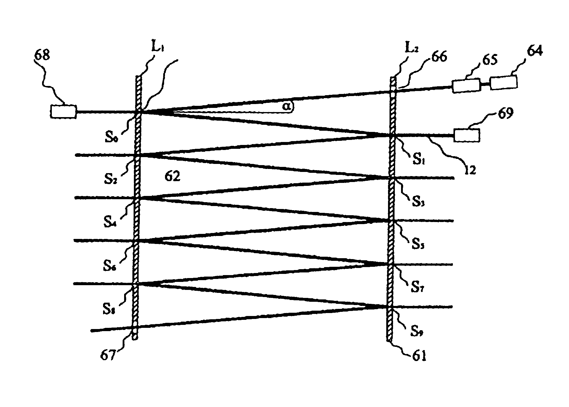
[0043]The apparatus shown in FIG. 5 comprises two parallel, flat, partially-reflective mirrors 51,52 having a configuration akin to a Fabry Perot resonator. A source 53 directs a beam 54 of electromagnetic radiation onto the facing surface of mirror 52. The beam is incident on this surface at a small angle (typically less than 10°) with respect to the normal and so undergoes multiple reflections between the facing surfaces of the mirrors, as shown in the drawing.

[0044]With this arrangement, the beam 54 is constrained to follow a predetermined, extended path between the mirrors, being alternately reflected at each mirror at successive positions spaced apart equidistantly from each other along the path.

[0045]A number of detectors is provided to measure the unreflected parts of the electromagnetic radiation at different positions D along the extended path followed by the beam. As will be described in greate...


PUM

PropertyMeasurementUnit
angleaaaaaaaaaa
wavelength rangeaaaaaaaaaa
reflection coefficientaaaaaaaaaa

Abstract

An apparatus for measuring decay in intensity of electromagnetic radiation passing through a radiation-absorbent sample due to absorption of radiation by the sample is disclosed which includes a source of electromagnetic radiation having a wavelength within an absorption band of the sample and a plurality of partially-reflective specular surfaces which are spaced apart from each other along a predetermined path through the sample, each specular surface separating the incident radiation into a reflected part which follows the predetermined path and an unreflected path, the value of the decay being derived from intensity measurements of the unreflected parts made at different positions along the predetermined path.

Description

FIELD OF THE INVENTION[0001]This invention relates to an apparatus and method for measuring decay in intensity of electromagnetic radiation passing through a radiation-absorbent sample due to absorption by the sample.[0002]The apparatus and method can be used, inter alia, to obtain a value of a sample a parameter, such as the concentration of absorbent atoms or molecules related to the decay in intensity.BACKGROUND OF THE INVENTION[0003]Absorption Spectroscopy has long been a tool in the analytical chemists' repertoire of analytical techniques. The fundamental theory is based on the observation that atoms and molecules absorb energy from electromagnetic radiation of a particular wavelength, typically, but not exclusively in the form of photons passing through a sample. As each atom or molecule has a distinctive pattern of absorption wavelengths it is possible to deduce the atomic or molecular species under analysis. It is also possible to obtain a measure of the concentration of the...

Claims


Application Information

Patent Timeline
Patent Type & Authority Patents(United States)
IPC IPC(8): G01N21/03G01J3/42G01N21/35
CPCG01N21/031
Inventor SMITH, ALAN JOSEPH
Owner SHIMADZU RES LAB EURO
Why Eureka
Try Eureka