Thin-film inspection method and device

a thin film and inspection method technology, applied in semiconductor/solid-state device testing/measurement, instruments, material analysis, etc., can solve the problems of difficult adjustment of these conditions, inability to obtain optimal inspection conditions, and inability to detect minute defects or determine inspection conditions

Inactive Publication Date: 2005-09-06
LG ELECTRONICS INC
View PDF5 Cites 67 Cited by
  • Summary
  • Abstract
  • Description
  • Claims
  • Application Information

AI Technical Summary

Benefits of technology

[0013]Therefore, the present invention has been made in view of the above problems, and it is an object of the present invention to provide a method and a device for inspecting a thin film wherein two or more light sources, which can control the wavelength and intensity of light and illuminate the lights with different incident angles, are used to control the interference intensity, thereby determining optimal inspection conditions to obtain a reliable inspection result even when there are different kinds of thin films.

Problems solved by technology

Presence / absence and shortage / excess of the pattern or contamination by foreign substances have a serious influence on the resulting product.
However, this optical system is not suitable for detecting minute defects or determining inspection conditions on the pattern, or for performing a high-speed inspection using a linear CCD because an illuminator suitable for an area CCD is used.
When this method is used, optimal inspection conditions closely depend on the characteristics of the thin-film pattern, but it is very difficult to adjust these conditions.
Therefore, when there are different kinds of patterns, or the characteristics of the pattern are changed, the optimal inspection condition cannot be obtained.
This inspection method cannot meet such needs.
However, when there are two or more films having different properties, this method cannot determine one inspection condition suitable for all the various kinds of properties of films.
As a result, if inspection conditions for a specific thin film are optimized, inspection conditions for a different thin film are degraded.
Consequently, the prior art thin-film inspection methods have problems that it is difficult to set an inspection condition when there are various kinds of thin films, and therefore their optimal inspection conditions become different under a particular condition, lowering the reliability of the inspection result.
However, the prior arts are very difficult to increase the relative sensitivity between patterns, and do not have an appropriate adjustment method for heterogeneous patterns.

Method used


Image

  • Thin-film inspection method and device
  • Thin-film inspection method and device
  • Thin-film inspection method and device

Examples


Embodiment Construction

[0034]Hereinafter, an embodiment of the present invention is described in detail referring to the drawings.

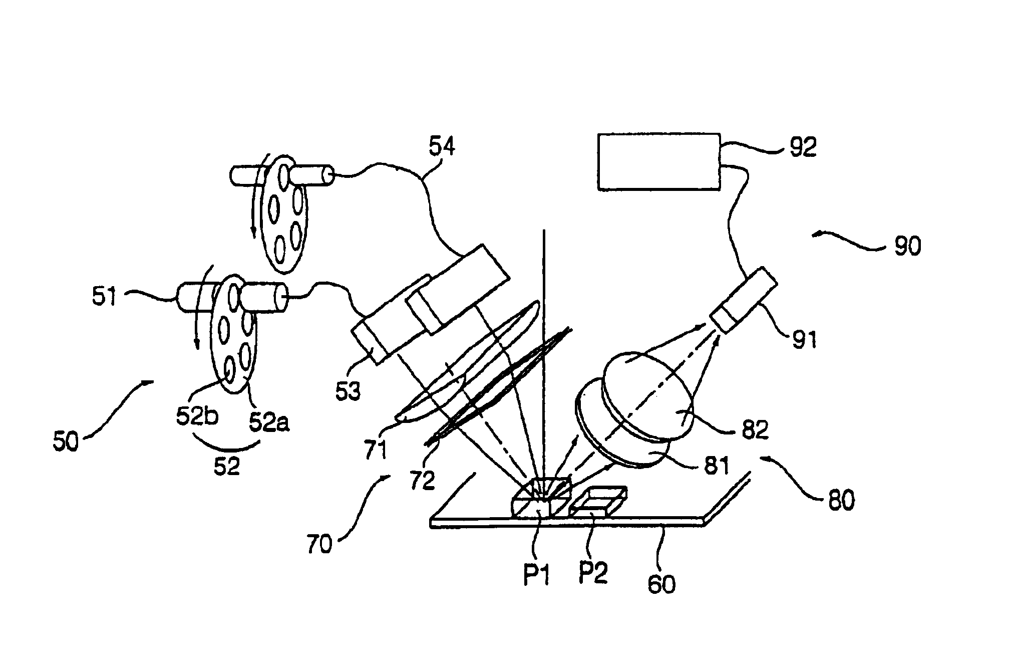
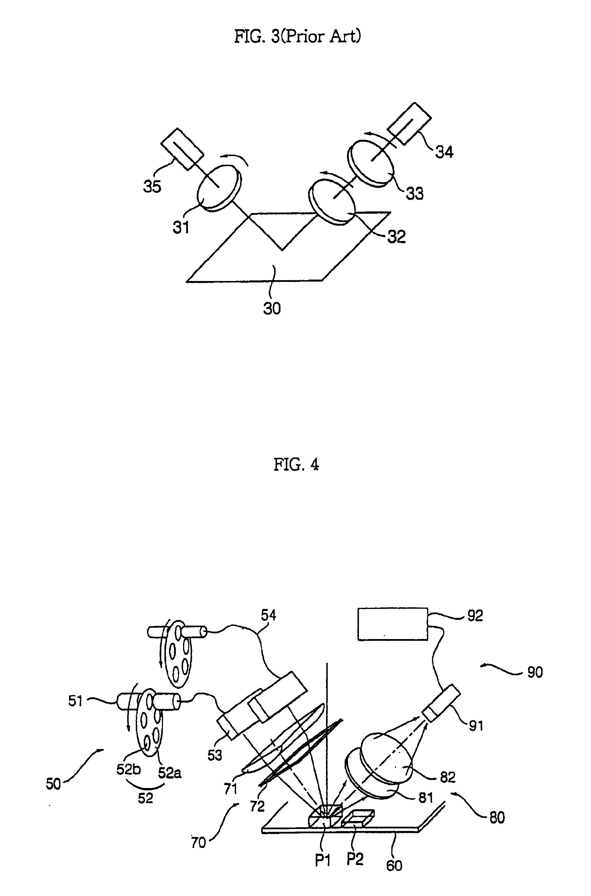
[0035]A thin-film inspection method according to the present invention includes a step of irradiating lights at different incident angles toward a flat plate, on which thin films with different thickness and indices of refraction are formed, using a plurality of independent light sources; a step of detecting interference light reflected from the thin films using a sensor; and a step of analyzing the detected light to obtain analysis information, so as to determine the state of the thin films.

[0036]In the light illumination step, it is possible to perform a real-time control of the irradiation angle and wavelength of the illuminated light, and to control the incident angle of the light by the horizontal movement of the movement of the light source.

[0037]In the light detection step, an image sensitivity of a particular material can be controlled by selectively detecting the wavel...


PUM

PropertyMeasurementUnit
wavelengthaaaaaaaaaa
incident angleaaaaaaaaaa
optical interferenceaaaaaaaaaa

Abstract

Disclosed is a thin-film inspection device with two or more light sources. This device can control the wavelength and intensity of light and illuminate the lights with different incident angles, and are used to control the interference intensity, thereby determining optimal inspection conditions to obtain a reliable inspection result even when different kinds of thin films coexist. The thin films are formed on a flat plate and have different indices of refraction and thicknesses. An incident light control unit is disposed between the illumination unit and the flat plate for controlling the light to be incident on the patterns. A sensor unit detects a reflection light from the patterns. A reflection light control unit is disposed between the flat plate and the sensor unit and controls the light to be detected by the sensor unit. A control unit controls the movement of the illumination unit and the sensor unit.

Description

BACKGROUND OF THE INVENTION[0001]1. Field of the Invention[0002]The present invention relates to a method and a device for inspecting thin films which are widely employed in a semiconductor manufacturing process, and more particularly to a method and a device for inspecting thin films wherein the surfaces of the thin films are inspected using an optical interference phenomenon, thereby allowing the inspection irrespective of the kind of film.[0003]2. Description of the Related Art[0004]Thin-film inspection is very important in manufacturing products such as LCD and PDP that use semiconductor processing mainly composed of processes of deposition, exposure, and etching. In the case of TFT LCD, thin films with thicknesses less than 1000 Å are piled up to form a pattern. Presence / absence and shortage / excess of the pattern or contamination by foreign substances have a serious influence on the resulting product. Accordingly, it is necessary to inspect the thin film for forming the pattern...

Claims


Application Information

Patent Timeline
Patent Type & Authority Patents(United States)
IPC IPC(8): G01B11/06G01B11/30G01N21/956H01L21/027H01L21/66
CPCG01B11/0675G01B11/30
Inventor JUNG, BOO YONGLIM, DAE CHEOLKIM, KYUNG GU
Owner LG ELECTRONICS INC
Why Eureka
Try Eureka