Electromagnetic band gap microwave filter

a microwave filter and electromagnetic band gap technology, applied in the field of electromagnetic band gap microwave filter, can solve the problems of ebg structure blocking the transmission of signal, increasing the demand for high-performance electronic filters, and increasing the demand for electronic filters

Active Publication Date: 2005-09-13
NXP USA INC
View PDF4 Cites 57 Cited by
  • Summary
  • Abstract
  • Description
  • Claims
  • Application Information

AI Technical Summary

Problems solved by technology

Such signal congestion has increased the demand for high performance electronic filters.
Designing passive RF components in the microwave region is, however, particularly challenging.
The issue of insertion losses is of particular concern in portable wireless devices that rely on batteries for power.
However, at frequencies that are within the band gap, EBG structures block the transmission of the signal.
When electr

Method used


Image

  • Electromagnetic band gap microwave filter
  • Electromagnetic band gap microwave filter
  • Electromagnetic band gap microwave filter

Examples


Embodiment Construction

[0022]Electromagnetic Band Gap (EBG) or Photonic Band Gap (PBG) crystals offer a powerful method of controlling the propagation of Electromagnetic (EM) waves. To understand the basic concepts involved, we draw an analogy with electronic semiconductor materials. Crystalline semiconductors are composed of a periodic arrangement of a basic building block of atoms. Therefore, a crystal in this context can be considered a periodic potential that a propagating electron encounters. Thus, the geometry and symmetry of the crystal dictates many of the conduction properties of the crystal. In particular, due to Bragg-like diffraction from the periodic potential, electrons are forbidden to propagate with certain energies in certain directions. If the periodic potential is strong enough, the gap might extend to all possible directions resulting in a complete band gap. For instance, an insulator has a complete band gap between the valence and conduction energy bands.

[0023]In EBG or PBG crystals, ...


PUM


Abstract

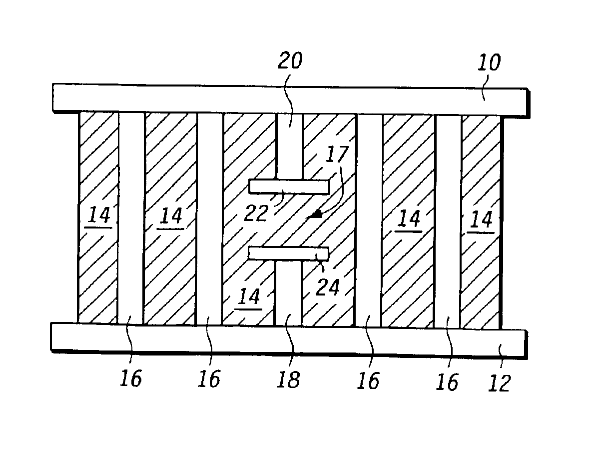
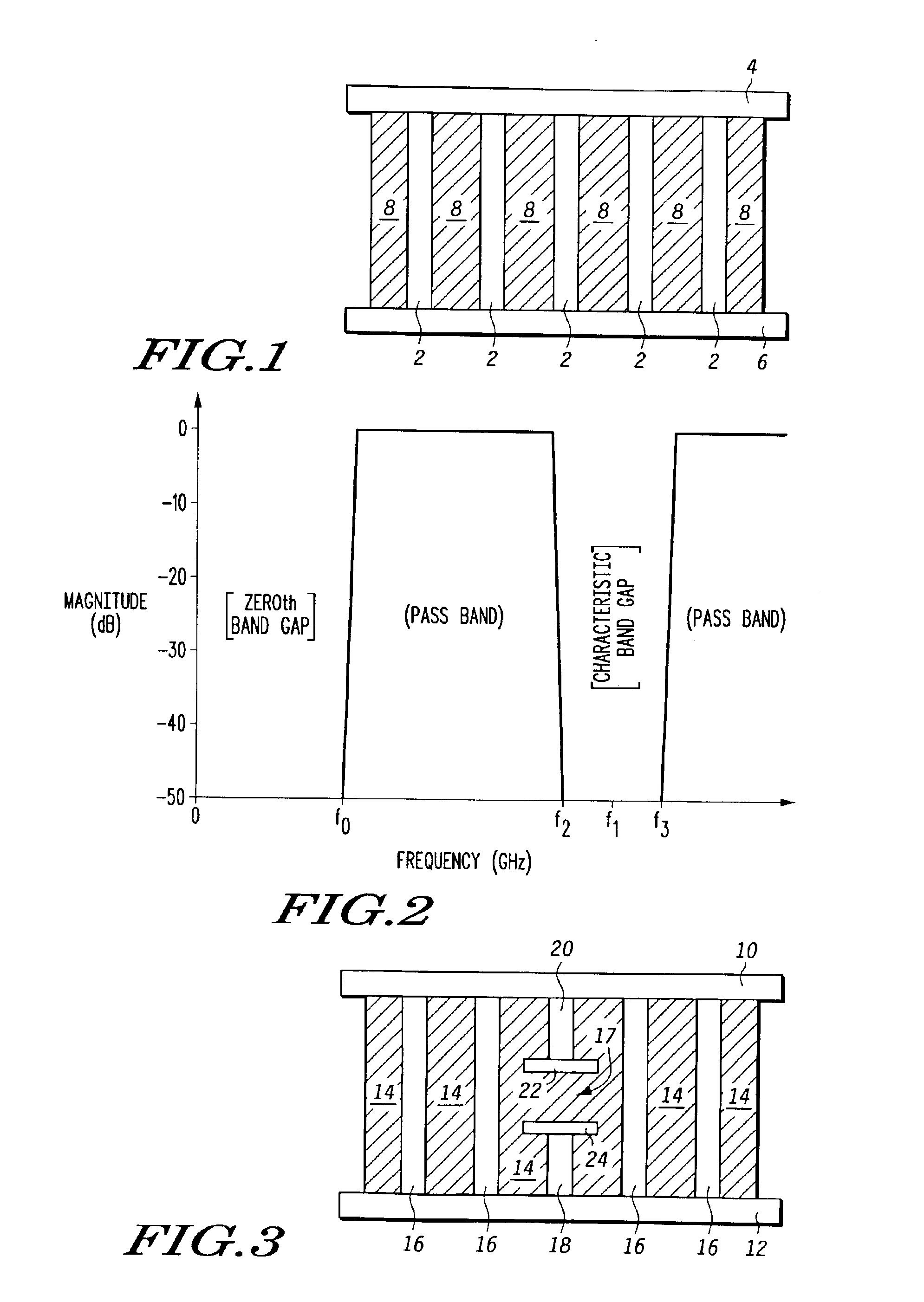
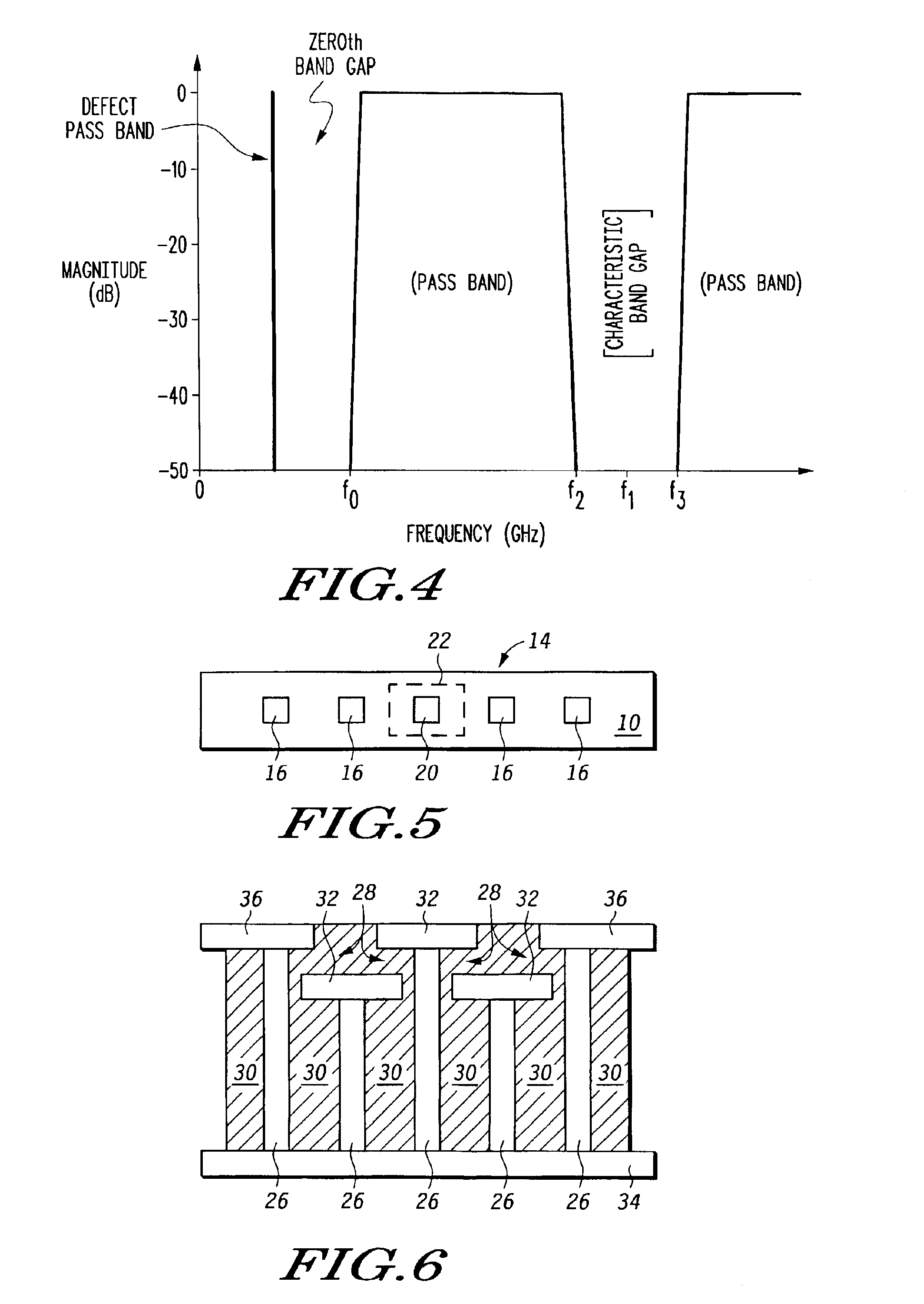
A microwave filter is formed from an electromagnetic band gap structure. The electromagnetic band gap structure includes a periodic array of metal features (16, 42, 44, 50) formed within a dielectric matrix (14, 52). A defect feature (17, 48) is formed within the periodic array of metal features (16, 42, 44, 50) in order to create a pass band within a stop band region.

Description

FIELD OF THE INVENTION[0001]The present invention relates to the field of electronic filters, and more particularly to filters constructed from materials having an electromagnetic band gap.BACKGROUND OF THE INVENTION[0002]Filters are widely employed to modify the frequency response of electronic circuits. Filters typically use pass or stop bands to modify the frequency response of a circuit by selectively transmitting or attenuating one or more frequencies within a spectrum. Filters may exhibit low pass, high pass, band pass, and band rejection attributes.[0003]Wireless communications has greatly crowded the electromagnetic spectrum. Such signal congestion has increased the demand for high performance electronic filters. In particular, filters that function at microwave frequencies are particularly important in wireless communications. Designing passive RF components in the microwave region is, however, particularly challenging. For wireless applications, notch filters that have a n...

Claims


Application Information

Patent Timeline
IPC IPC(8): H01P1/20
CPCH01P1/20H01P1/2005
Inventor RAMPRASAD, RAMAMURTHYPETRAS, MICHAEL F.
Owner NXP USA INC
Why Eureka
Try Eureka