Nuclear reactor

a nuclear reactor and reactor technology, applied in nuclear reactors, nuclear elements, greenhouse gas reduction, etc., can solve the problems of increasing increasing the number of pipes, pumps, heat exchangers or steam generators, and complication or increase in the size of the cooling system, so as to facilitate convection and efficient conversion

Inactive Publication Date: 2005-09-13
CENTRAL RESEARCH INSTITUTE OF ELECTRIC POWER INDUSTRY
View PDF30 Cites 51 Cited by
  • Summary
  • Abstract
  • Description
  • Claims
  • Application Information

AI Technical Summary

Benefits of technology

[0007]It is an object of the present invention to provide a nuclear reactor in which a cooling system is simplified and which is suitable for a reduction in size of a nuclear steam supply system.
[0010]Based on this, the cooling system outside the reactor vessel can be simplified, and a nuclear steam supply system and a reactor containment can be reduced in size, thereby decreasing a facility cost. Furthermore, since the cooling system can be simplified, monitoring targets can be reduced, maintenance management of the nuclear steam supply system can be simplified in terms of both personnel and facilities, thus reducing their costs. Moreover, since the small nuclear steam supply system can be inexpensively manufactured, a use of the nuclear reactor as a dispersion-type power source can be facilitated.
[0012]In this nuclear reactor, since the heat transfer tube is arranged in the reactor vessel and heat of the primary coolant is transmitted to the fluid of the water / steam system in the reactor vessel, an intermediate heat exchanger and a steam generator independent from the reactor vessel are no longer necessary, thereby simplifying the cooling system. Therefore, the nuclear reactor in which the cooling system is constituted of the primary coolant system and the secondary coolant system can be reduced in size. Accordingly, the small nuclear reactor which is suitable for a dispersion-type power source can be inexpensively manufactured, thereby facilitating a use of the nuclear reactor.
[0015]In this nuclear reactor, heat transfer from the primary coolant to the secondary coolant is carried out through the first heat transfer tube arranged in the inner vessel, and heat transfer from the secondary coolant to the tertiary coolant is performed through the second heat transfer tube arranged between the inner vessel and the outer vessel. Therefore, heat of the reactor core can be safely exploited outside the double vessel (reactor vessel) without using an intermediate heat exchanger and a steam generator independent from the reactor vessel, and a structure that the primary coolant system and the secondary coolant system are integrated in the double vessel is adopted, thereby greatly reducing the number of tubes and the like. Thus, the cooling system is simplified, and the nuclear steam supply system including the three systems, i.e., the primary coolant system, the secondary coolant system and the tertiary coolant system and the reactor containment can be reduced in size, thereby decreasing a facility cost. Furthermore, since the cooling system can be simplified, the maintenance management of the nuclear steam supply system becomes simple, thus reducing its cost. Moreover, since the small nuclear steam supply system can be inexpensively manufactured, a use of the nuclear reactor as a dispersion-type power source can be facilitated.
[0018]Here, it is preferable that the first heat transfer tube is an erected straight tube. In this case, a movement of the second coolant in the first heat transfer tube, e.g., an upward movement is most efficiently converted into a force to facilitate the convection of the first coolant, e.g., a downward force, thereby provoking a stronger circulation. Further, it is preferable to forcibly circulate the secondary coolant by providing a pump at an inlet part of the first heat transfer tube. In this case, heat transfer from the secondary coolant to the tertiary coolant is increased as a flow quantity of the secondary coolant which circulates in the first heat transfer tube becomes large and, at the same time, a force to facilitate the convection of the primary coolant formed by the magnetic flux generating means is also increased and a circulation quantity of the primary coolant becomes higher. Furthermore, heat transfer from the primary coolant system to the secondary coolant system is increased, and hence the entire cooling efficiency is increased.

Problems solved by technology

In the above-described nuclear reactor of the indirect cycle, however, since transmission of heat between the respective cooling systems is carried out by the steam generator or the heat exchanger which is independent or integrated in each chamber and connected through a pipe, the entire cooling system becomes complicated and large.
Therefore, the number of pipes, pumps, heat exchangers or steam generators and others is increased, and complication or an increase in size of the cooling system is prominent.
Therefore, a manufacturing cost of a nuclear steam supply system (HSSS: including the nuclear reactor, the secondary and subsequent cooling systems, the heat exchanger and the steam generator) reaches a huge value, and its maintenance management requires many work forces and monitoring facilities, and hence a large amount of cost is needed.
However, the intermediate heat exchanger or the steam generator is still required, it cannot be said that simplification or a reduction in size of the cooling systems is sufficient, and further simplification or a reduction in size of the cooling systems is demanded.

Method used


Image

  • Nuclear reactor
  • Nuclear reactor
  • Nuclear reactor

Examples


first embodiment

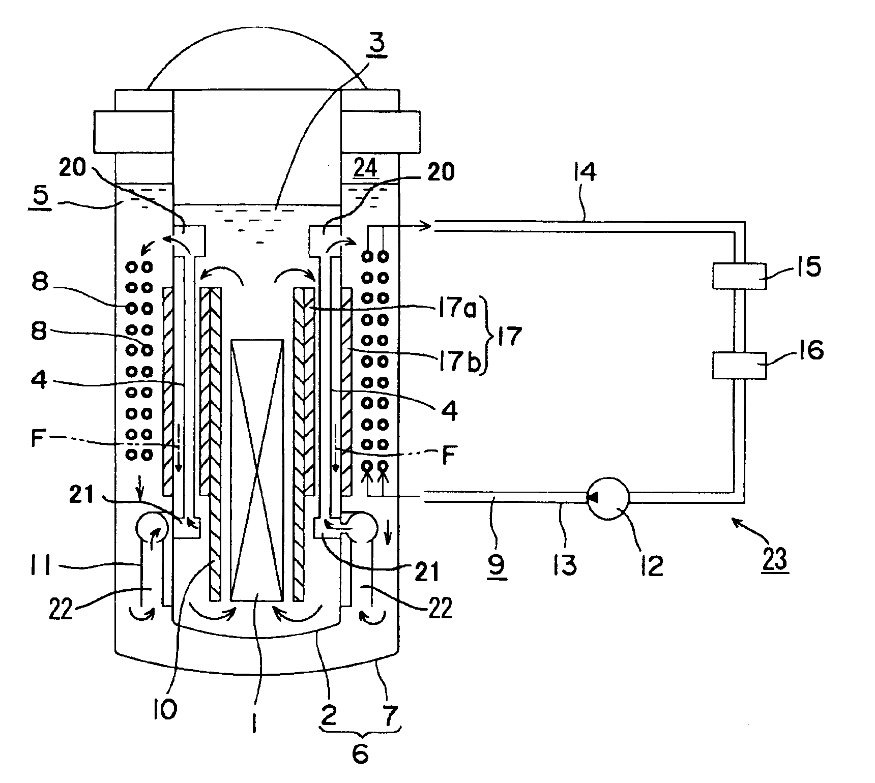
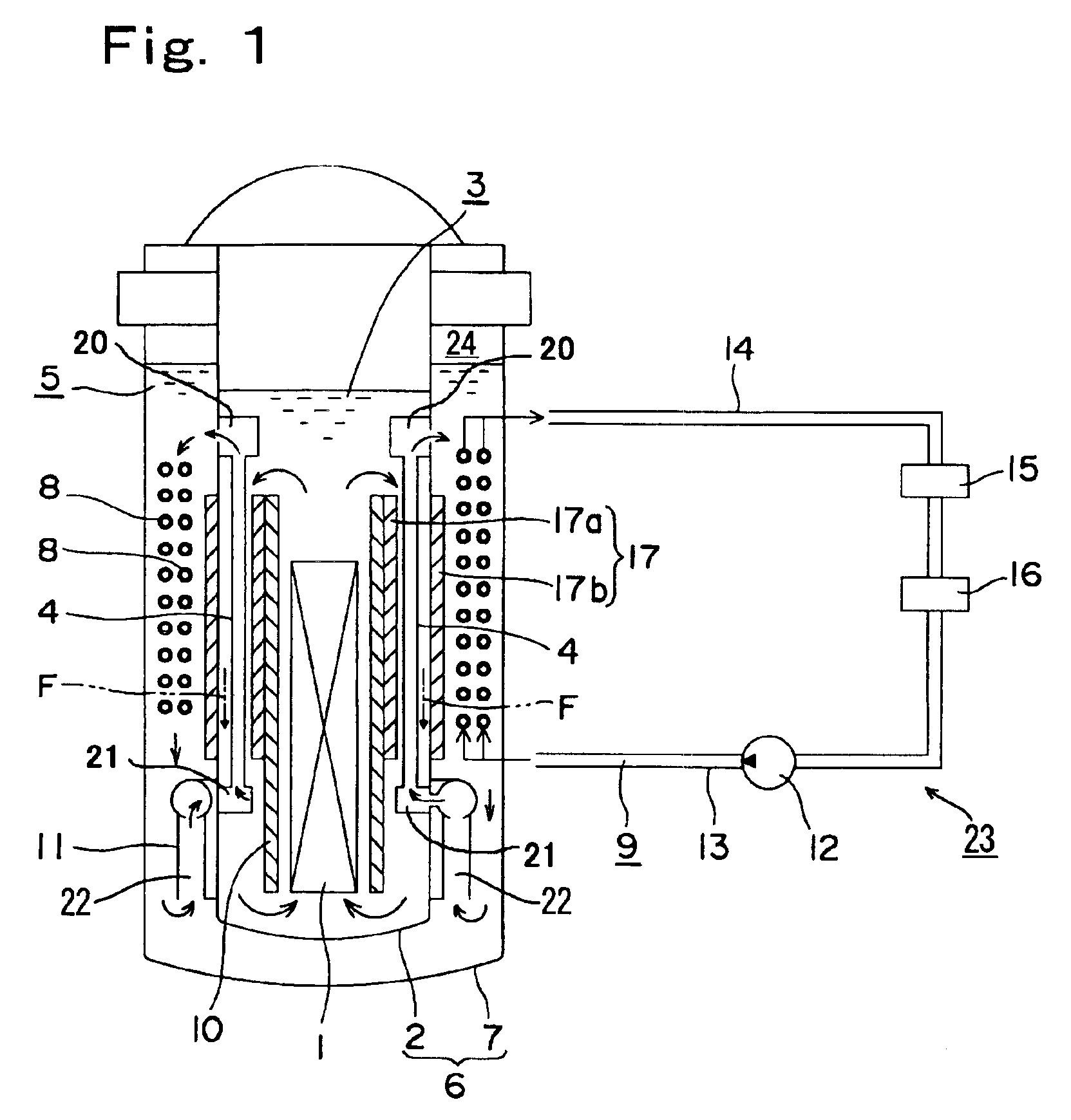
[0023]FIG. 1 shows a nuclear reactor according to the present invention. This nuclear reactor includes: a reactor vessel 2 which integrates therein a reactor core 1; a first coolant 3 which is stored in the reactor vessel 2, and heated by the reactor core 1 to convect; a first heat transfer tube 4 which is arranged in the reactor vessel 2 and comes into contact with the first coolant 3; and a second coolant 5 which is supplied from the outside of the reactor vessel 2 to the first heat transfer tube 4, cools the first coolant 3 and led to the outside of the reactor vessel 2. The reactor vessel 2 is an inner vessel of a double vessel 6 (which will be referred to as an inner vessel 2 in this embodiment), the first coolant 3 is a primary coolant (which will be referred to as a primary coolant 3), and the second coolant 5 is a secondary coolant (which will be referred to as a secondary coolant 5 in this embodiment) which is stored between an outer vessel 7 and the inner vessel 2 of the d...

second embodiment

[0039]the nuclear reactor according to the present invention will now be described with reference to FIG. 3. It is to be noted that like reference numerals denote the same constituent elements as those in the nuclear reactor shown in FIG. 1.

[0040]A cooling system of this nuclear reactor is constituted of a primary coolant system and a water / steam system 23 which flows through heat transfer tubes 4 running in a reactor vessel 2 and removes heat of a primary coolant. That is, the nuclear reactor includes: a reactor vessel 2 which integrates therein a reactor core 1; a first coolant 3 which is stored in the reactor vessel 2, heated by the reactor core 1 to convect; a heat transfer tube 4 which is arranged in the reactor vessel 2 and comes into contact with the first coolant 3; and a second coolant 5 which is supplied from the outside of the reactor vessel 2 to the heat transfer tube 4, cools the first coolant 3 and led to the outside of the reactor vessel 2. The first coolant 3 is a pr...


PUM


Abstract

A nuclear reactor in which a secondary or tertiary coolant system of a nuclear steam supply system is simplified, comprising: a reactor vessel (2) which integrates a reactor core (1); a first coolant (3) which is stored in the reactor vessel (2) and heated by the reactor core (1) to convect; a first heat transfer tube (4) which is arranged in the reactor vessel (2) and comes into contact with the first coolant (3); and a second coolant (5) which is supplied from the outside of the reactor vessel (2) to the first heat transfer tube (4), cools the first coolant (3) and led to the outside of the reactor vessel (2).

Description

TECHNICAL FIELD[0001]The present invention relates to a nuclear reactor. More particularly, the present invention relates to a nuclear reactor in which a cooling system is divided into at least a primary system and a secondary system.BACKGROUND ART[0002]In a nuclear reactor of an indirect cycle which generates electric power by rotating a turbine with steam which is not contaminated by radiation, a steam generator or a heat exchanger is provided between the primary coolant system and the secondary coolant system.[0003]For example, in a loop-type fast breeder, heat of a primary sodium system (primary coolant system) heated by cooling a reactor core is transmitted to a secondary sodium system (secondary coolant system) by an intermediate heat exchanger, and heat of the secondary sodium system is transmitted to a water / steam system by an evaporator and a superheater. Further, in a pool-type fast breeder reactor in which a reactor vessel is increased in size and a pump of a primary sodi...

Claims


Application Information

Patent Timeline
Patent Type & Authority Patents(United States)
IPC IPC(8): G21C15/02G21C15/00G21C1/00G21C1/02G21C1/32G21C15/247
CPCG21C1/32G21C15/02G21Y2002/301G21Y2004/30Y02E30/40Y02E30/30
Inventor HATTORI, SADAOUOTANI, MASAKIUEDA, NOBUYUKI
Owner CENTRAL RESEARCH INSTITUTE OF ELECTRIC POWER INDUSTRY
Why Eureka
Try Eureka