

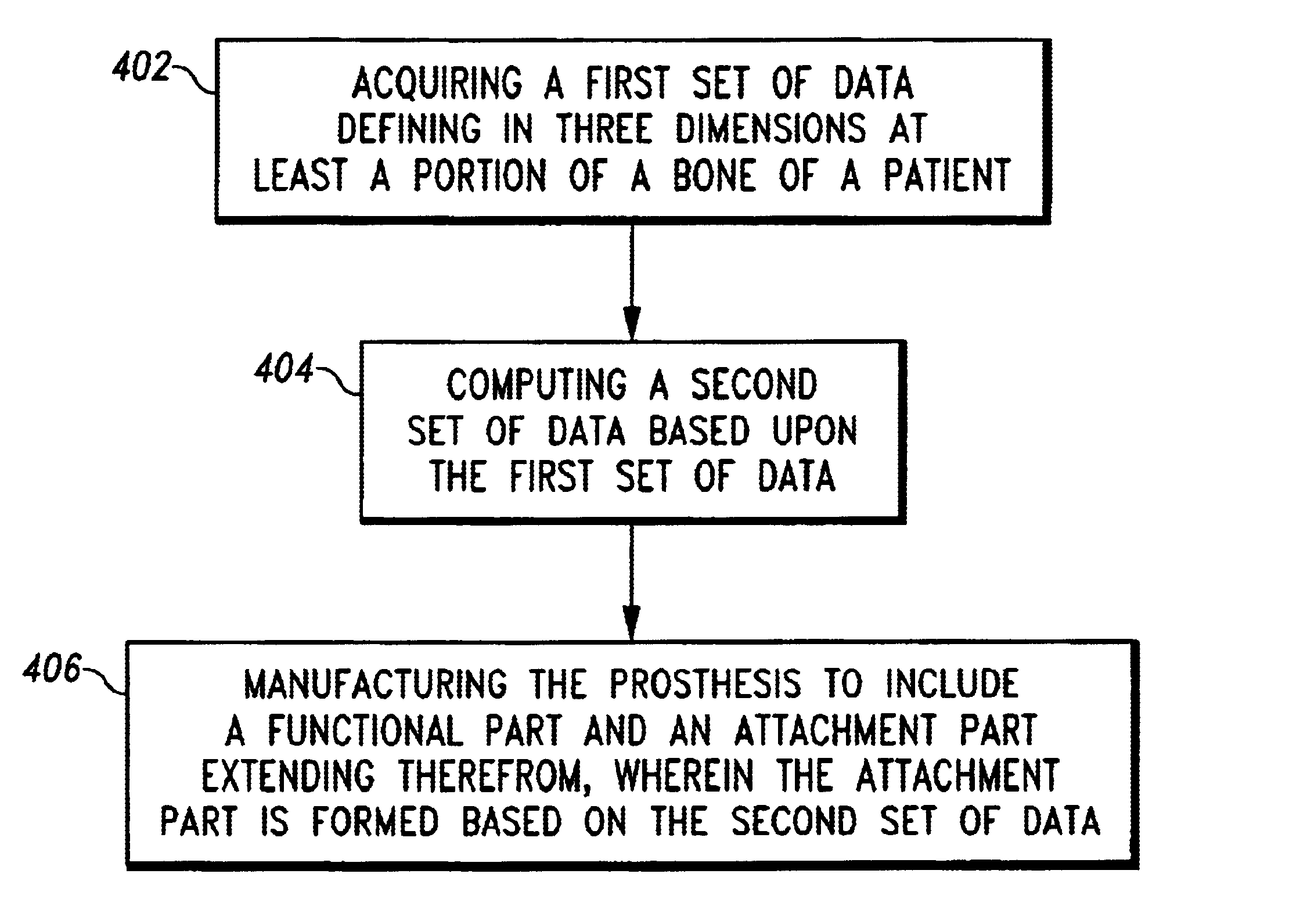
Customized prosthesis and method of designing and manufacturing a customized prosthesis by utilizing computed tomography data
a computed tomography and customization technology, applied in the field of customized prostheses, can solve the problems of difficulty in reaming a properly sized cavity in the acetabulum, and insufficient seated of the acetabular cup in the cavity of the acetabulum, so as to reduce the surgical time required for implantation of the prosthesis, the effect of quick preparation
- Summary
- Abstract
- Description
- Claims
- Application Information
AI Technical Summary
Benefits of technology
Problems solved by technology
Method used
Image

Examples
Embodiment Construction
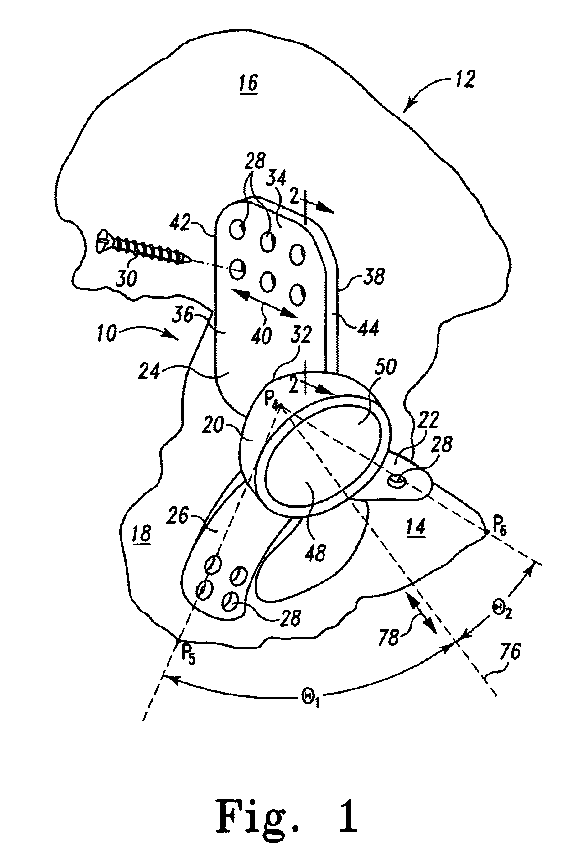
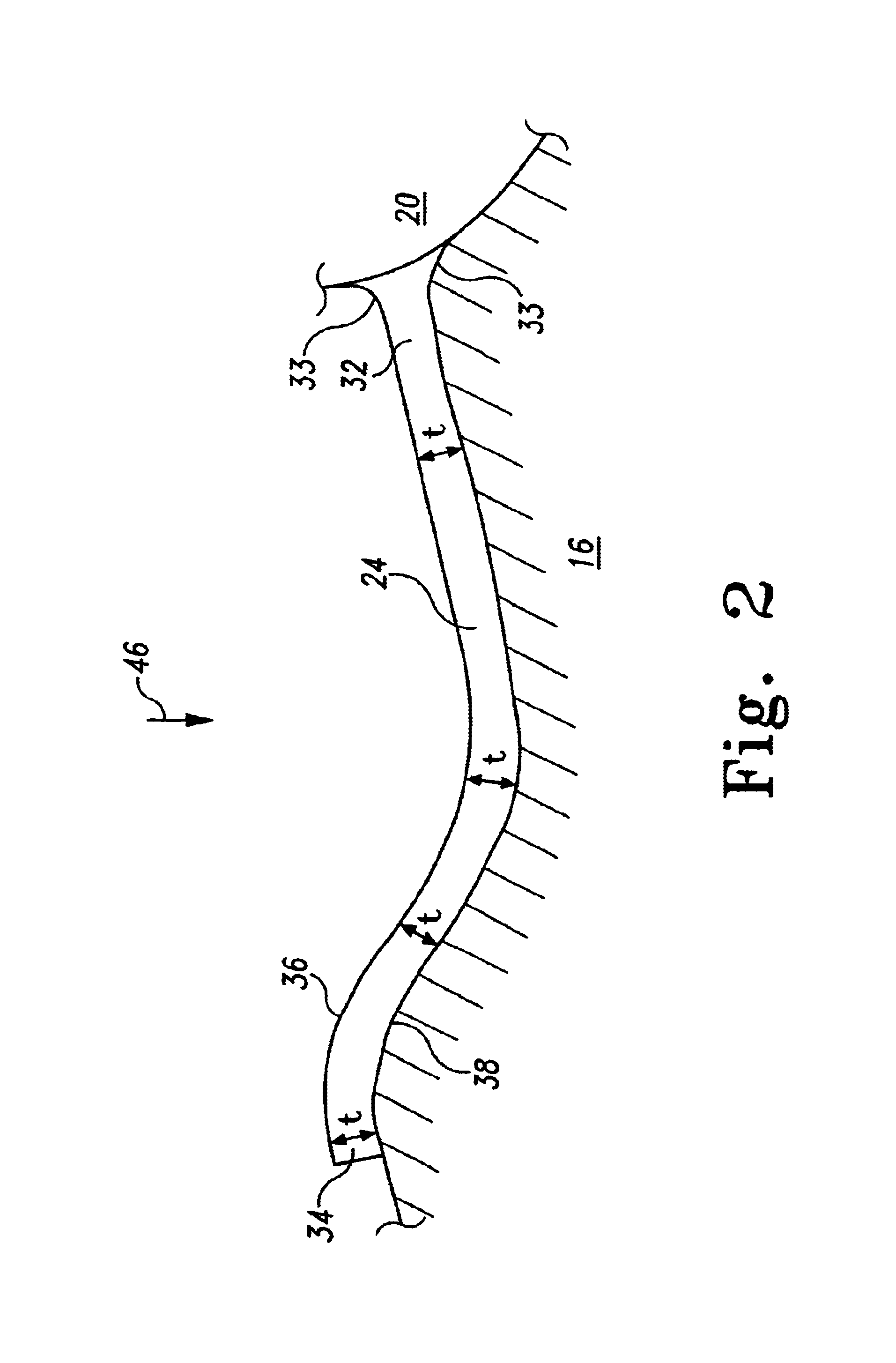
[0033]For the purposes of promoting an understanding of the principles of the invention, reference will now be made to the embodiments illustrated in the drawings and described in the following written specification. It is understood that no limitation to the scope of the invention is thereby intended. It is further understood that the present invention includes any alterations and modifications to the illustrated embodiments and includes further applications of the principles of the invention as would normally occur to one skilled in the art to which this invention pertains.
[0034]Referring to FIG. 1, there is depicted one embodiment of the subject invention comprising an acetabular prosthesis, generally designated 10, and an associated pelvic arch bone structure 12, also known as the innominate bone, including a pubis 14, ilium 16 and ischium 18. The acetabular prosthesis 10 is configured for replacement surgery in which the patient's entire hip joint is replaced. Compactness of th...
PUM
 Abstract
Description
Claims
Application Information