Container closure system

a container and closure technology, applied in the field of container closure system, can solve the problems of overtightening or stripping of the thread connection between the closure and the container, the inability of practical cleaning systems to remove all milk residue and deposits from the milk contact surface, and the application of threaded closures to milk containers, etc., to achieve the effect of simplifying and facilitating the application of threaded caps, preventing stripping of caps, and reducing the number of moving and fixed parts

Inactive Publication Date: 2005-09-20
BLACKHAWK MOLDING
View PDF21 Cites 28 Cited by
  • Summary
  • Abstract
  • Description
  • Claims
  • Application Information

AI Technical Summary

Benefits of technology

[0006]When the turret rotates, a pinion gear at or near the upper end of the drive shaft of the spindle assembly delivers torque to the drive shaft due of the engagement of the pinion gear with a stationary and much larger gear wheel mounted atop the turret. In a typical turret capping machine the gear wheel is continuous. However, as shown in U.S. Pat. No. 5,473,855, the gear wheel may be less than a full circle, and torque may be delivered to the drive shaft intermittently. The interface where torque is transferred from gripping jaws on the chuck to knurls formed on the outside surface of the cap (i.e., the chuck / cap interface) is designed to prevent stripping of the cap as it is tightened onto the threads of the container.
[0007]In one embodiment described herein, a cap is designed to have a series of areas where some of the knurls on the exterior of the skirt portion of the cap extend radially outwardly beyond other knurls, such that the extended knurls are the primary points of contact with the gripping jaws of the chuck. If the cap tightens before the spindle assembly stops rotating, the extended knurls deflect and allow continued rotation of the chuck, even though the cap has stopped rotating, thus preventing the stripping of the threads of the cap relative to the threads on the container neck.
[0008]Thus, the knurls on the cap and splines on the jaws inside the chuck as described herein are specifically designed to simplify and facilitate the application of threaded caps to threaded containers. The chuck / cap interface described and claimed herein is designed to reduce the number of moving and fixed parts by eliminating the need for a clutch mechanism in a capping spindle. This objective is achieved the a chuck and cap combination that includes a very simple and easily cleaned chuck and a cap with a specially designed surface that is contacted by the jaws of the chuck.
[0009]Furthermore, the simplicity of chuck described and claimed herein significantly reduces down time needed to clean and disinfect the capping machine and reduces the chance of unwanted bacteria from making its way into any bottles.

Problems solved by technology

It is nearly impossible with practical cleaning systems to remove all milk residues and deposits from the milk contact surfaces of milk bottling and capping equipment.
One of the major difficulties with most currently used equipment, closures and containers, is the need to thoroughly and frequently clean the equipment so that the contents of the containers is not contaminated.
Overtightening or stripping of the threaded connection between the closure and the container is also a problem.
Applying threaded closures to milk containers is particularly problematic because milk is lubricious, making stripping a significant problem in milk bottling operations.
Because many bottlers do not have expertise in blow molding operations and, in particular, tooling maintenance, serious problems can arise, such as bottles being molded to configurations which significantly vary over time.
In some instances, bottlers have other difficulties maintaining consistent quality in the manufacture of their bottles.
Problems such as excessive flash, mismatching of mold components, excessive parison pleating, and non-round openings are common in on-site blow molding operations.
While caps are generally molded to relatively precise and consistent dimensions, blow molded bottles generally are not, particularly bottles made by bottlers who blow mold bottles on-site.
To provide a reliable closure on bottles of varying dimensions and quality is a difficult challenge for cap suppliers.

Method used


Image

  • Container closure system
  • Container closure system
  • Container closure system

Examples


Embodiment Construction

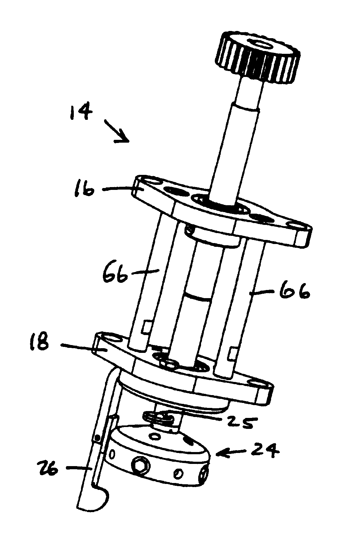
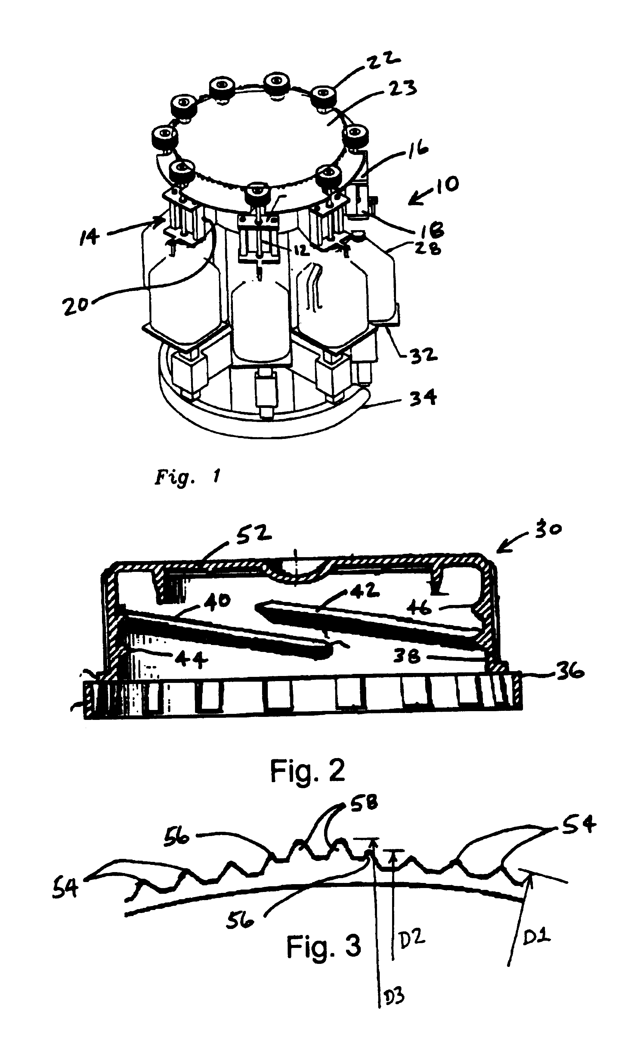
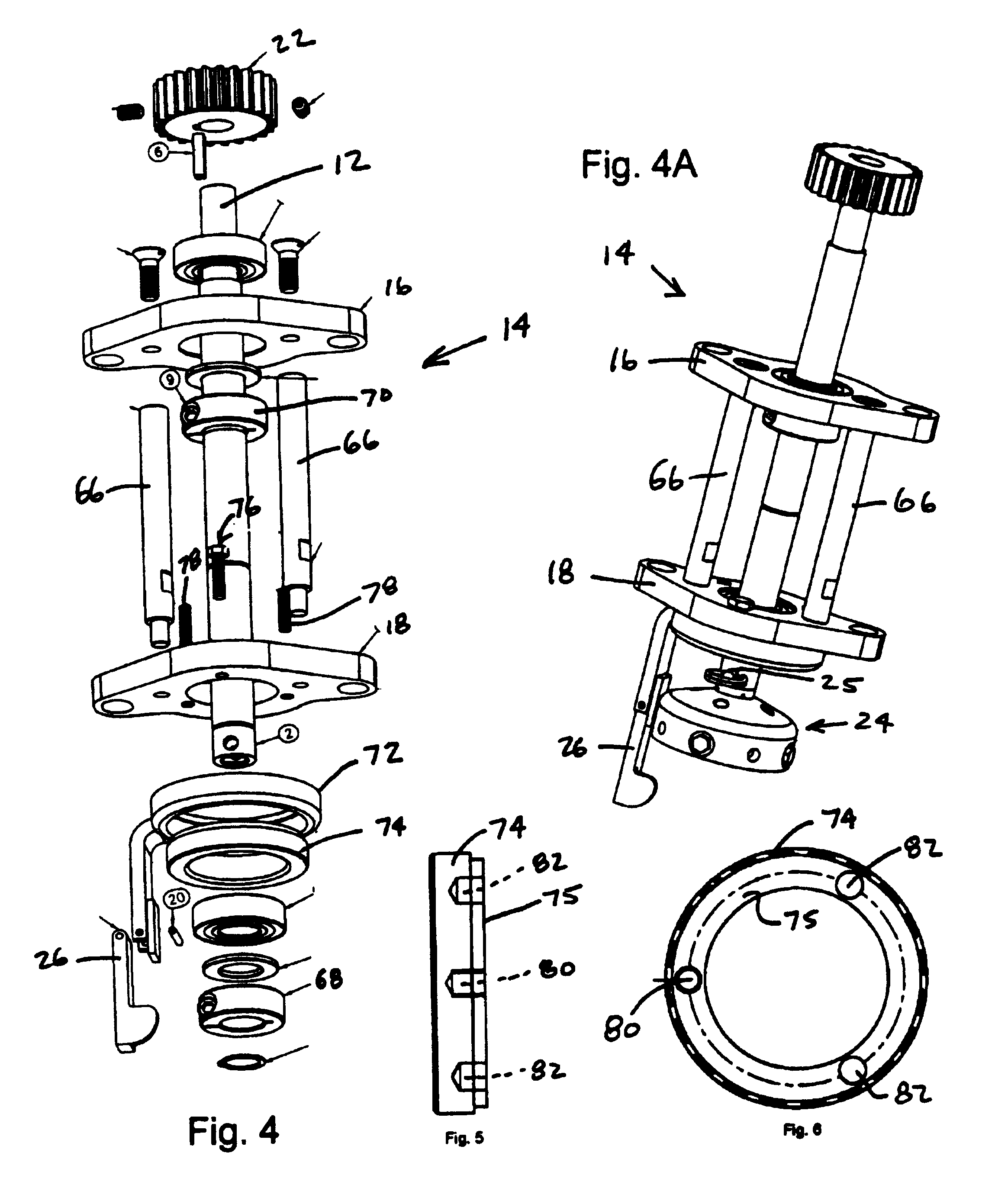
[0024]FIG. 1 shows a turret assembly 10 with several capping stations. Each capping station includes a spindle assembly 14 held in place by a pair of support plates 16 and 18. The spindle assembly includes drive shaft 12 which is held and guided by an upper support plate 16 and a lower support plate 18. The support plates 16 and 18 are connected to the turret assembly 10 by a spindle support arm 20. A small pinion gear 22 is affixed to the upper end of the drive shaft 12, and a chuck 24 (shown in detail in FIGS. 4 and 4A) is connected, by a quick-release pin 25, to the lower end of the drive shaft 12. Attached to the lower support plate 18 is a hinged stop arm 26 which engages the handle of a bottle 28 to prevent rotation of the bottle as a cap 30 (shown in detail in FIGS. 2 and 3) is tightened onto the bottle 28.

[0025]As the turret 10 rotates in the direction of the arrow shown in FIG. 1, a bottle support 32, carried by the turret assembly 10, engages a cam 34, and lifts each bottl...


PUM


Abstract

A system for sealing threaded containers. The system includes a clutch-free spindle assembly which is easily disassembled and cleaned. The special interface between the exterior surface of the cap an the gripping jaws of the chuck allow the system to operate without the moving parts and complications that attend the use of clutch. The spindle assembly features an easily adjustable stop arm and a quick release pin for removing and cleaning the chuck. The chuck has several passageways for the rapid infusion of cleaning fluid.

Description

BACKGROUND AND SUMMARY OF THE INVENTION[0001]Machines for applying closures to containers are well known and widely used. The present invention relates to the application of threaded closures to containers having threaded necks, and is particularly directed to the application of closures to containers which hold consumable liquids, such a milk.[0002]It is nearly impossible with practical cleaning systems to remove all milk residues and deposits from the milk contact surfaces of milk bottling and capping equipment. One of the major difficulties with most currently used equipment, closures and containers, is the need to thoroughly and frequently clean the equipment so that the contents of the containers is not contaminated.[0003]Overtightening or stripping of the threaded connection between the closure and the container is also a problem. Applying threaded closures to milk containers is particularly problematic because milk is lubricious, making stripping a significant problem in milk...

Claims


Application Information

Patent Timeline
Patent Type & Authority Patents(United States)
IPC IPC(8): B67B3/20B67B3/00B65B7/28
CPCB67B3/00B67B3/2033B67B3/2073B65B7/2828
Inventor HIDDING, DOUGLAS J.BASHOUR, JOSEPH E.
Owner BLACKHAWK MOLDING
Why Eureka
Try Eureka