
Gas flow sensor having redundant flow sensing capability

Inactive Publication Date: 2005-09-20
GENERAL ELECTRIC CO
View PDF13 Cites 78 Cited by
  • Summary
  • Abstract
  • Description
  • Claims
  • Application Information

AI Technical Summary

Benefits of technology

[0004]It is, therefore, the object of the present invention to provide a redundant gas flow sensing system having small size and low cost thereby to overcome the current shortcomings in providing highly reliable and certain flow sensing in critical applications such as those involving patient care.
[0007]The present invention obtains redundant flow sensing capabilities with small size and cost by providing a flow sensor having a housing suitable for being interposed in a conduit, the gas flow in which is to be measured. The housing has an orifice through which the gas to be measured flows. A gas flow measuring hot wire anemometer is positioned in the housing proximate the orifice for providing a measurement of the gas flow in the conduit. A first absolute pressure sensor is located to measure gas pressure downstream, of the orifice. The first pressure sensor provides pressure compensation to the gas flow measurement of the anemometer.
[0009]The gas flow sensor of the present invention measures the gas flow using two different physical phenomena. The first is that of the hot wire anemometer. The pressure sensors use a second physical phenomenon, the difference in pressure as the gas passes through the orifice. This is desirable because it increases the reliability of the redundant measurement of the gas flow rate. This invention is also suitable to measure the flow rates in multiple gas supply conduits connected to a common mixing conduit. Only one downstream pressure sensor in the mixing conduit is needed to measure the differential pressure for any number of gas supply conduits.
[0010]The gas flow sensor of the present invention provides accurate measurements with compensation for changes in temperature and / or atmospheric or system pressures. The temperature sensor in the anemometer flow sensor also provides temperature compensation for the redundant differential pressure flow measurement. Additionally, the use of two absolute pressure transducers avoids the need for internal pressure compensation because the gas flow measurement is a relative differential pressure measurement.

Problems solved by technology

While these types of flow sensors can provide accurate measurement of gas flow in an anesthesia machine or ventilator, an essential problem exists in such an application of protecting the patient against a fault or failure of a flow sensor.
However, the addition of another stand-alone flow sensor increases the complexity, size, and cost of the flow sensing components.
Also, an additional stand-alone flow sensor may introduce an additional pressure drop in the gas supply line impeding or preventing proper operation of the apparatus.

Method used


Image

  • Gas flow sensor having redundant flow sensing capability
  • Gas flow sensor having redundant flow sensing capability
  • Gas flow sensor having redundant flow sensing capability

Examples


Embodiment Construction

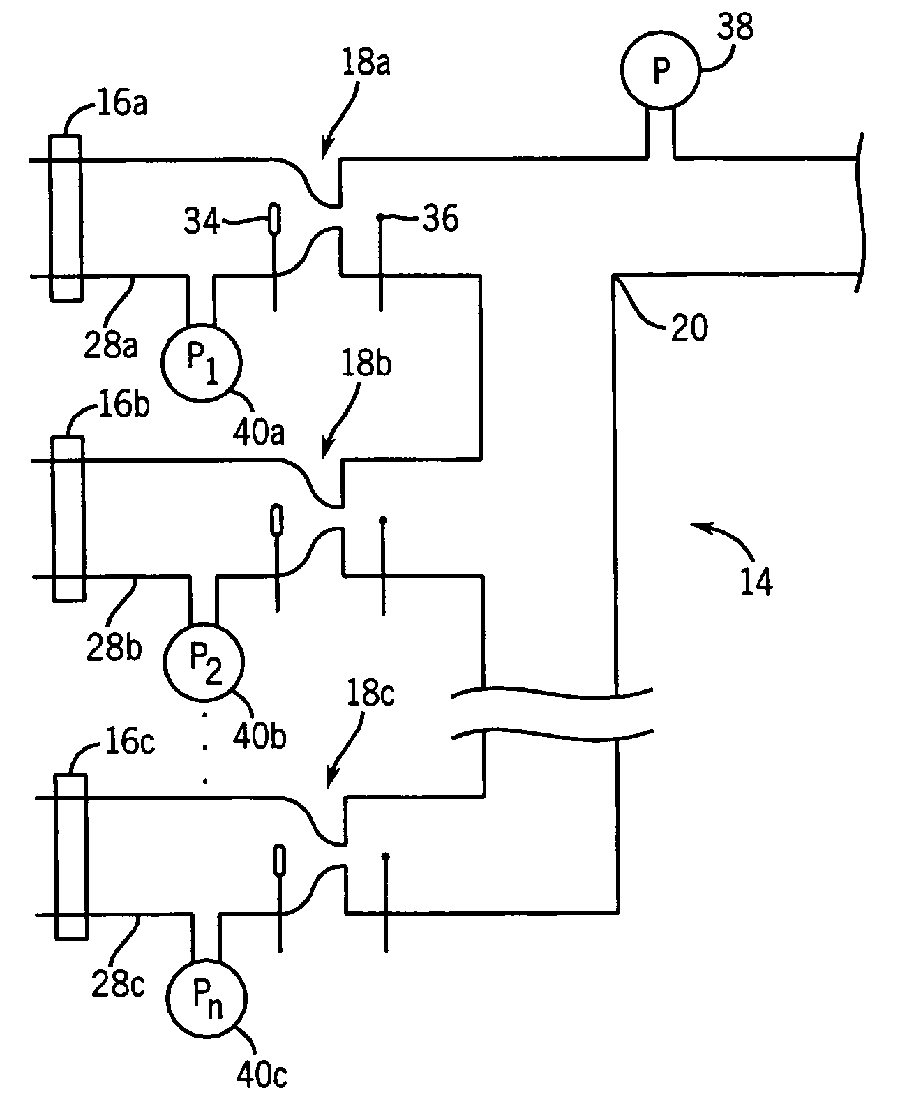
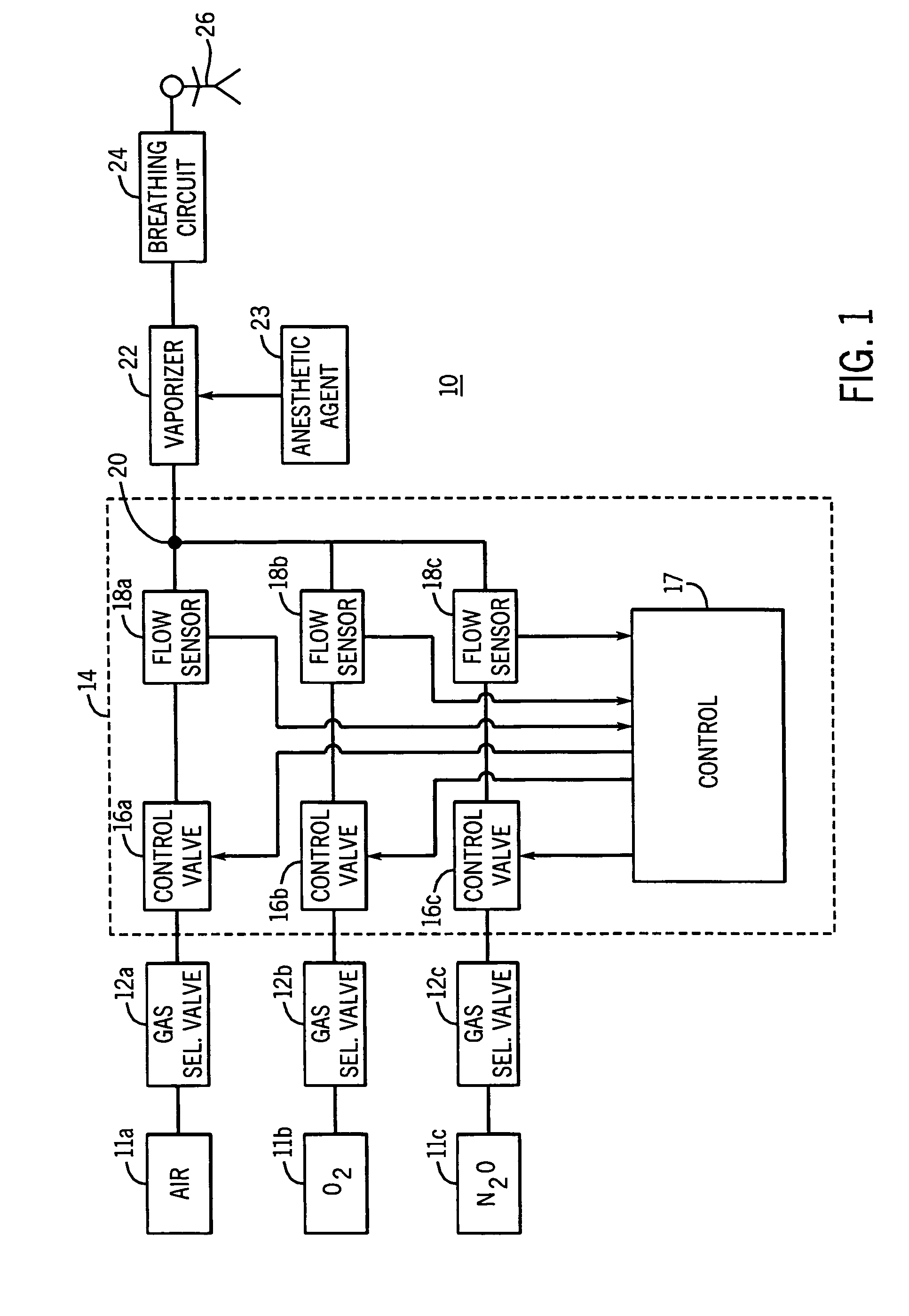
[0016]The redundant gas flow sensor of the present invention is shown in FIG. 1 in an application in which breathing gases are being provided to a patient in a medical setting. FIG. 1 shows a block diagram of an anesthesia machine 10 which is typically supplied with a plurality of medical gases, such as air, oxygen, and nitrous oxide, from pressurized sources 11a, 11b, 11c, respectively. The sources are connected to gas selector valves 12a, 12b, and 12c and to a gas mixer 14. For each of the gases, the gas mixer 14 includes a control valve, control valves 16a, 16b, and 16c, and a flow sensor 18, flow sensors 18a, 18b, and 18c, which may comprise the redundant flow sensor of the present invention. Control valves 16a, 16b, and 16c and flow sensors 18a, 18b, and 18c are connected to control 17 that operates the valves responsive to the gas flows sensed by the sensors and to other inputs. The gases from sources 11a, 11b, and 11c are combined to form a mixed gas at mixed gas outlet 20. T...


PUM


Abstract

A sensor for redundantly measuring gas flow has a housing suitable for being interposed in a gas flow conduit. The housing has an orifice through which the gas to be measured flows. A gas flow measuring, hot wire anemometer is positioned in the housing proximate to the orifice for providing a first measurement of the gas flow in the conduit. A first absolute pressure sensor measures gas pressure downstream of the orifice. The first pressure sensor may provide pressure compensation to the anemometer. A second absolute pressure sensor measures gas pressure upstream of the orifice. The first pressure sensor may be further used with the second pressure sensor to obtain a differential pressure measurement providing a further measurement of the gas flow in the conduit that is redundant to that of the anemometer.

Description

[0001]The present invention relates to gas flow sensors having redundant flow sensing capabilities. While not so limited, such a sensor finds particular utility in medical equipment for measuring gas flow rates in anesthesia machines and ventilators and is described in that context, below.BACKGROUND OF THE INVENTION[0002]Anesthesia machines and ventilators provide breathing gases to a patient in a clinical setting. These breathing gases are formed by mixing gases from supplies of compressed gas such as air, oxygen, and nitrous oxide. To insure proper concentrations of the gases, flow sensors are needed in supply lines for the gases to measure the flow rates of the different, component, gases forming the breathing gases given to the patient. Many types of flow sensors are available for this application including, but not limited to, differential pressure, hot wire anemometer, turbine, and ultrasound sensors.[0003]While these types of flow sensors can provide accurate measurement of g...

Claims


Application Information

Patent Timeline
IPC IPC(8): G01F1/34A61M16/00A61M16/01A61M16/18G01F1/36G01F1/50G01F1/68G01F15/04
CPCA61M16/01G01F1/36G01F1/50G01F1/68G01F15/046A61M16/18A61M16/183A61M2016/0039A61M2205/17
Inventor KUEHL, KENNETH J.NELSON MOCK, KRISTEN E.MEYFERTH, DONALD C.
Owner GENERAL ELECTRIC CO
Features
  • Generate Ideas
  • Intellectual Property
  • Life Sciences
  • Materials
  • Tech Scout
  • Unparalleled Data Quality
  • Higher Quality Content
  • 60% Fewer Hallucinations
Learn More