Method and system for controlling the temperature of a dispensed liquid

Inactive Publication Date: 2005-09-20
APRECIA PHARMA LLC +2
View PDF11 Cites 123 Cited by
  • Summary
  • Abstract
  • Description
  • Claims
  • Application Information

AI Technical Summary

Benefits of technology

[0023]The present invention provides a new method and system for controlling the temperature of a dispensed liquid at the point of dispensing. One embodiment of the present invention includes a dispensing device such as a microvalve that introduces additional heat to the system through operation combined with a control to reduce the temperature of the liquid at the point of dispensing.

Problems solved by technology

In all of these, variable temperature of the dispensed liquid negatively impacted the quality and consistency of the droplet.
Precise temperature control of the printed liquid has not been adequately controlled, in part because traditional liquids and applications did not require it.
The result of this steeper slope was that even small shifts in temperature resulted in significant shifts in viscosity making it much more difficult to maintain a consistent flow pattern during dispensing.
Further, liquids heated to above ambient temperature were severely impacted by temperature variation because these substances may not be liquid at ambient temperature.
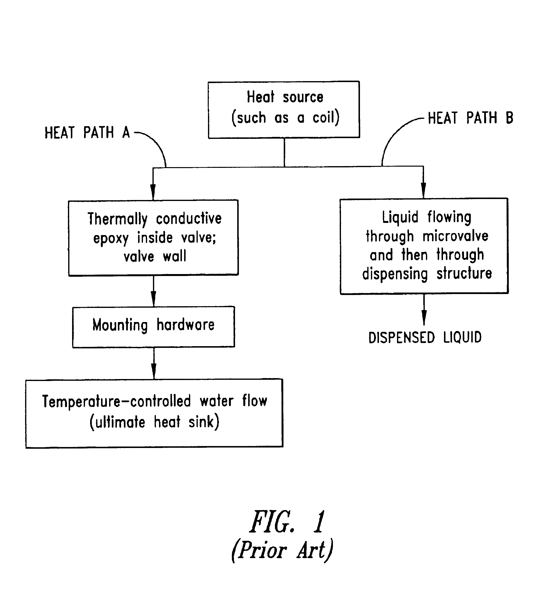
For use with hot-melt inks, tank heaters have been used to maintain a melted reservoir of the solder or wax, however, fluctuation in temperature at the point of dispensing continued to negatively impact print quality.
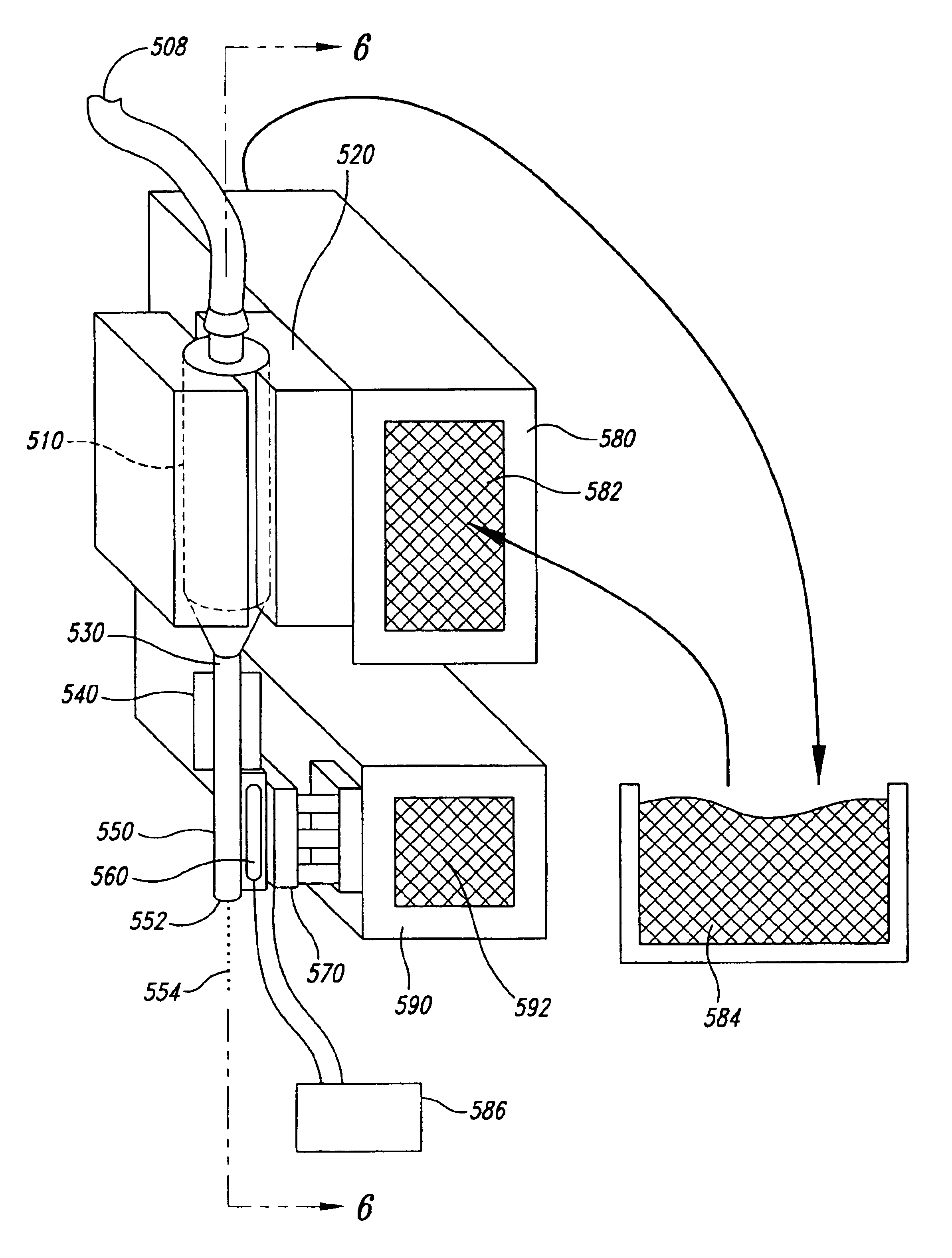
Most commonly in the past, inks, binder liquids and similar liquids have been dispensed at approximately ambient temperature, in the range of 20 to 25° C. However, solenoid valves or microvalves dissipate heat from an internal coil which is powered by an electrical waveform, thus impacting the quality of the printing.
However, in either previously used passive or active temperature control means, there was still some unavoidable and unacceptable temperature rise of the valve coil and variable heat dissipation, causing increased liquid temperature due to these temperature increases.
For precise dispensing of fluids, these variations are unacceptable due to the negative impact on the flow pattern of the printed liquid.
Changes in fluid viscosity result in unpredictable shifts to the 
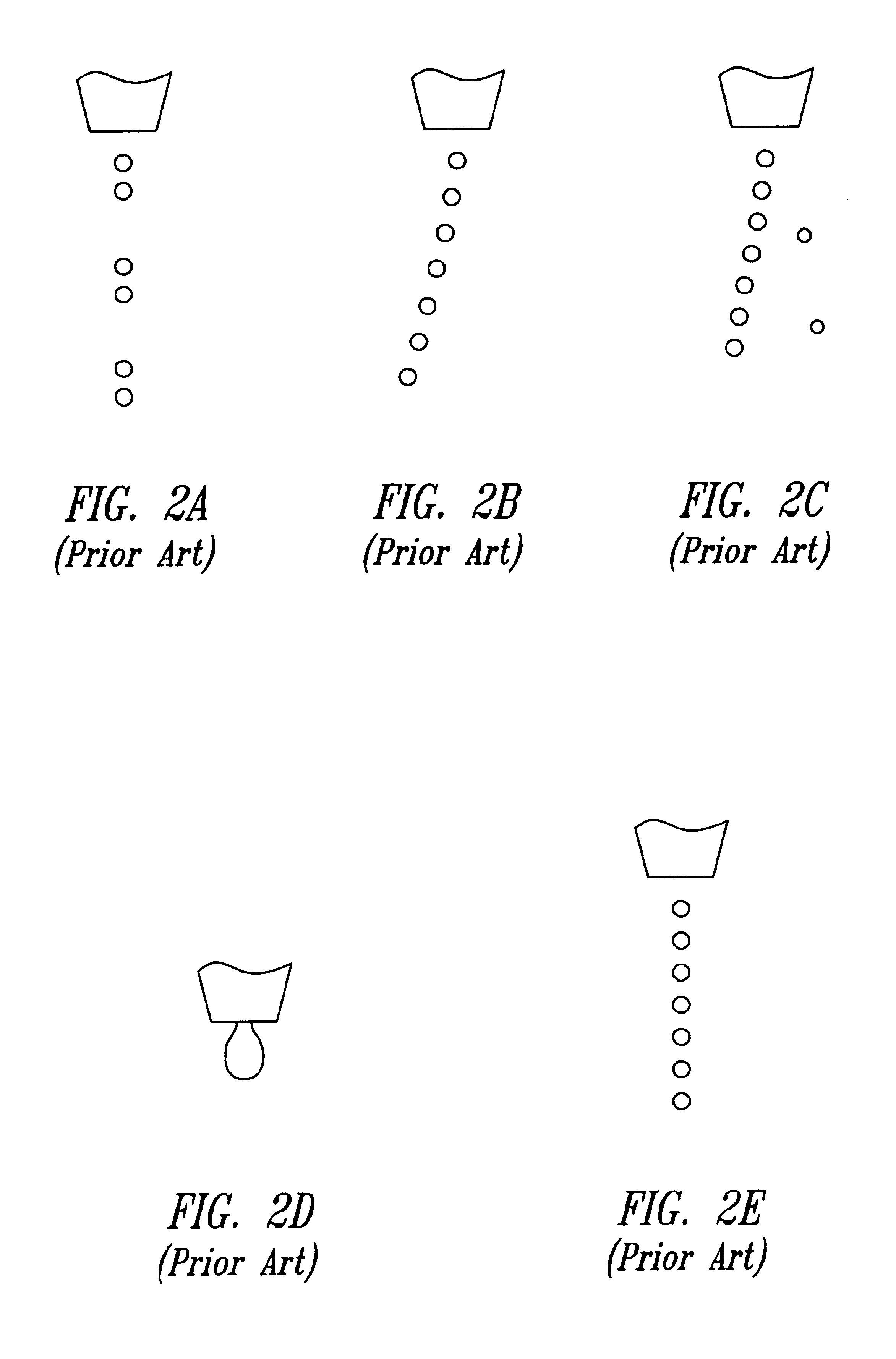
stream flow regime among the various patterns shown hereinafter.
Thus, the techniques described so far for managing the overall temperature of the microvalve body, for example, heat

Method used


Image

  • Method and system for controlling the temperature of a dispensed liquid
  • Method and system for controlling the temperature of a dispensed liquid
  • Method and system for controlling the temperature of a dispensed liquid

Examples


Embodiment Construction

[0036]A temperature control system, and in particular, a system and corresponding method for controlling the temperature of a dispensed liquid, is described in detail herein. In the following description, numerous specific details are provided, such as specific microvalve printhead configurations, piezoelectric dispensers, etc., to provide a thorough understanding of various embodiments of the invention. One skilled in the relevant art, however, will recognize that the invention can be practiced on various printhead dispenser configurations without one or more of the specific details, or configurations, methods, etc. In other instances, well-known structures or operations are not shown or not described in detail to avoid obscuring aspects of the invention.

[0037]Referring to the flowchart of FIG. 4, heat flow paths for a microvalve are illustrated in accordance with the present invention. A microvalve contains a heat source component such as solenoid 410 which generates heat. This he...


PUM


Abstract

A device for controlling or altering the temperature of a liquid at the point of dispensing. A temperature-altering device is thermally coupled to a dispensing device to compensate for heat dissipated into the liquid as it passes through the dispensing device during dispensing. The dispensing device may be for example, a miniature solenoid valve (microvalve), a piezoelectric printhead, or the like. According to aspects of the invention, a temperature-altering device provides or reduces heat at the point of dispensing in order to alter, control or maintain a constant temperature of the dispensed liquid. As a result, improvement is obtained in the consistency of the fluid regime of the dispensed droplet stream. The temperature-altering device may be a thermoelectric device capable of moving heat either from or to the dispensing structure, or may be a heater. This device may be used beneficially even when the dispensing is performed near room temperature and the liquid does not require heating to maintain its liquid state.

Description

[0001]This application claims benefit of U.S. Provisional Application 60 / 338,624 filed Oct. 29, 2001.BACKGROUND OF THE INVENTION[0002]1. Field of the Invention[0003]This invention relates generally to dispersing liquids from a printhead, and more particularly, to controlling the temperature of a dispensed liquid at the point of discharge.[0004]2. Description of the Related Art[0005]Dispensing and printing of small quantities of liquids have been done by any of several methods including miniature solenoid valves (microvalves), piezoelectric printheads, continuous-jet printheads, and bubble-jet printheads. In all of these, variable temperature of the dispensed liquid negatively impacted the quality and consistency of the droplet. Precise temperature control of the printed liquid has not been adequately controlled, in part because traditional liquids and applications did not require it. Currently, however, the need to print liquids with greater temperature sensitivity, as well as more ...

Claims


Application Information

Patent Timeline
IPC IPC(8): B01L3/02B41J2/05B41J2/02B41J2/015G05D23/19B41J29/377
CPCB01L3/0265B01L3/0268B41J2/02B41J2/04528B41J2/04563B41J29/377G05D23/1919B01L2200/147B01L2300/1805B01L2300/1827B01L2400/0439B01L2400/0487B01L2400/0633B41J2002/022
Inventor TEUNG, PATRICKCIMA, MICHAEL J.PRYOR, TIMOTHY J.MATERNA, PETER A.
Owner APRECIA PHARMA LLC
Why Eureka
Try Eureka