
In-situ thermochemical solidification of dense non-aqueous phase liquids

Inactive Publication Date: 2005-09-20
GAS TECH INST
View PDF3 Cites 16 Cited by
  • Summary
  • Abstract
  • Description
  • Claims
  • Application Information

AI Technical Summary

Benefits of technology

[0014]It is another object of this invention to provide a method for handling dense non-aqueous phase liquids which can be carried out in-situ, thereby avoiding the excavation required by conventional thermal desorption methods.
[0015]It is still a further object of this invention to provide a method for handling dense non-aqueous phase liquids which reduces the release rates of subsurface contaminants of concern to achieve risk based goals for the environmentally acceptable management of a site.
[0018]It is still another object of this invention to provide a method for handling dense non-aqueous phase liquids which eliminates the need for expensive post-treatment handling and disposal.
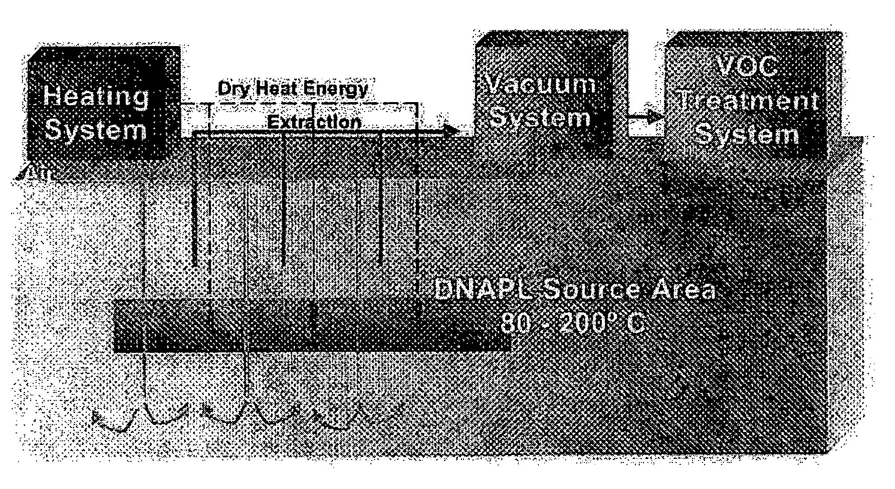
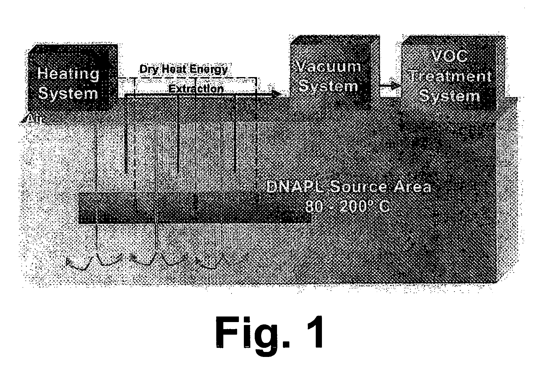
[0019]These and other objects of this invention are addressed by a method for in-situ dense non-aqueous phase liquids treatment, referred to herein as thermochemical solidification (TCS), comprising the steps of locating a subsurface source area comprising at least one rapid release contaminant, removing free water from the subsurface source area, heating the subsurface source area to a temperature suitable for extracting the at least one rapid release contaminant from the subsurface source area, and extracting the at least one rapid release contaminant from the subsurface source area, resulting in solidification of the dense non-aqueous phase liquids remaining in the subsurface source area. The method of this invention exploits the physical differences between the heavy and light fractions present in the dense non-aqueous phase liquids to effect an in-situ removal of the lower molecular weight compounds from the dense non-aqueous phase liquids mass, thereby leaving behind the higher molecular weight materials which are solidified when the light fraction is removed. The method of this invention can effectively treat either neat (concentrated) dense non-aqueous phase liquids or mixtures of dense non-aqueous phase liquids with soil, demolition wastes and / or sediment.
[0021]Thermochemical solidification technology has considerable potential to provide substantial benefits in terms of savings for the industrial and government sectors and in terms of performance and reliability of the thermal technologies applied to the DNAPL management. In general, it is expected that the technology will be applicable to the treatment of concentrated DNAPL in shallow and deep subsurface locations. In applying the risk-based thermochemical solidification approach, savings will arise from the following advantages:
[0024]3) Verifiable in effectiveness. New protocols for the contaminant “availability” to groundwater and other receptors from IGT make verification of reduced release rates in the source areas possible.Thermochemical solidification technology has considerable potential to provide substantial benefits for the industrial and government sectors, including the following: Substantial billion-dollar level savings nation-wide. Reduces cost of many commercial thermal treatment systems through:

Problems solved by technology

Conventional methods of applying thermal desorption to achieve in-situ removal of coal-based DNAPL have been less than highly successful.
Attempts to apply classical thermal desorption temperatures in-situ to achieve efficient removal of the total DNAPL mass have been largely unsuccessful due to the inability to reach the required target temperature range of 400°–700° C. using commercial heating hardware.
A further disadvantage of conventional thermal desorption methods is the large outputs of hydrocarbon contaminants resulting from the high temperature desorption that require expensive handling and disposal.
These limitations point to the need for a new strategy for the effective use of thermal treatment.

Method used


Image

  • In-situ thermochemical solidification of dense non-aqueous phase liquids
  • In-situ thermochemical solidification of dense non-aqueous phase liquids
  • In-situ thermochemical solidification of dense non-aqueous phase liquids

Examples


examples

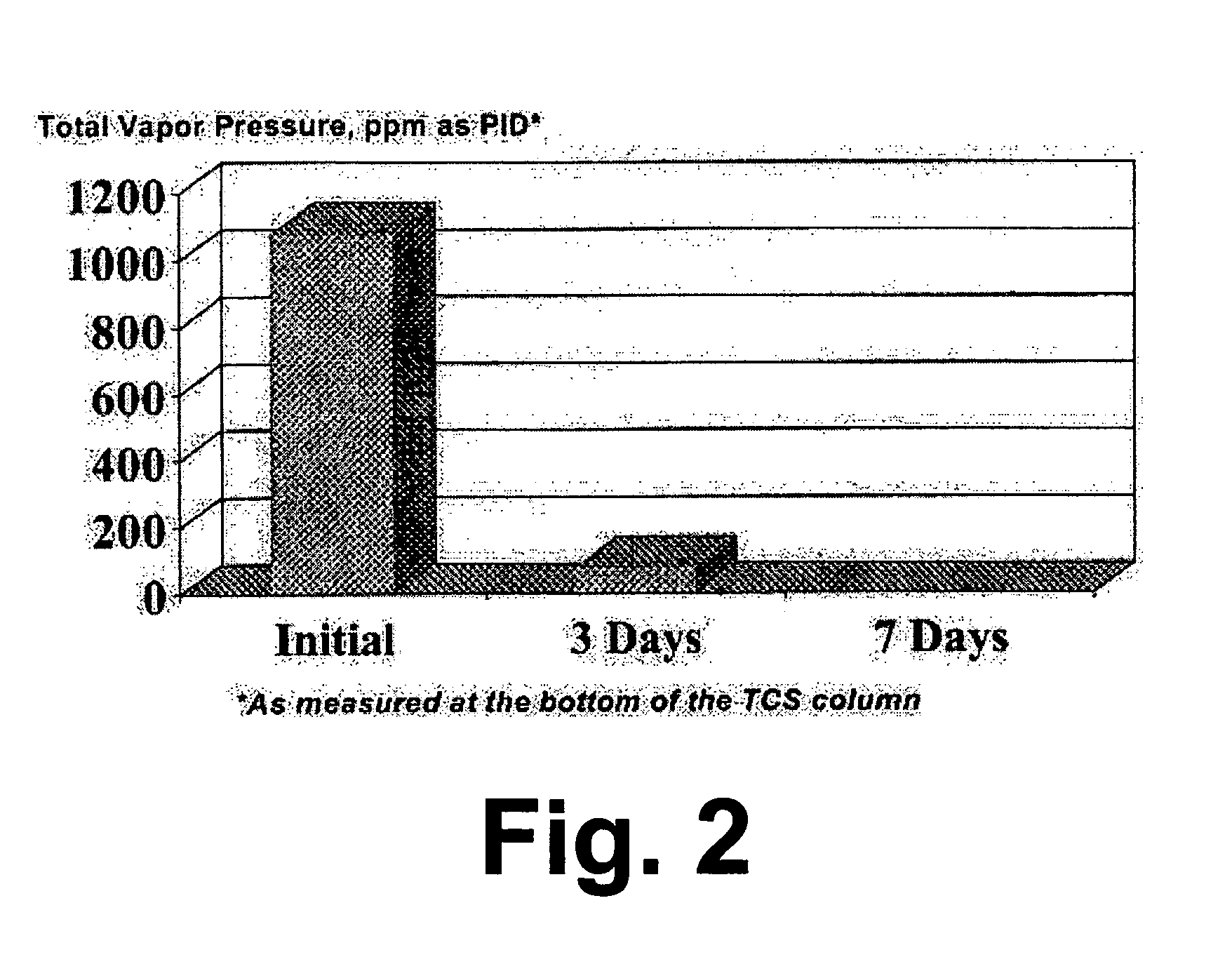
[0063]In this example, thermochemical solidification was applied to the treatment of dense non-aqueous phase liquids in a gas holder of an MGP site that was 50 feet in diameter and 22 feet deep. The holder had already been decommissioned and what remained is the subsurface holder tank that had been filled in with demolition materials and soil. Soil borings and PID profile measurements showed that high PID readings were obtained in a layer that extends from the bottom of the holder to 6 feet above the bottom of the holder. Contaminant mobility testing of soil samples showed that 90 percent of the rapid release fraction contaminant mass was located in the 6 ft dense non-aqueous phase liquids layer at the bottom of the holder. This layer was thus targeted for thermochemical solidification. The dense non-aqueous phase liquids layer contained some free water and the composition of the drained soil / dense non-aqueous phase liquids material was as follows: 1) DNAPL content=10%; 2) solubiliz...


PUM

PropertyMeasurementUnit
Temperatureaaaaaaaaaa
Lengthaaaaaaaaaa

Abstract

A method for in-situ dense non-aqueous phase liquids treatment in which a subsurface source area comprising at least one rapid release contaminant is located and free water removed therefrom. The subsurface source area is then heated to a temperature suitable for extracting the at least one rapid release contaminant from the subsurface source area. The at least one rapid release contaminant is extracted from the subsurface source area, resulting in solidification of the dense non-aqueous phase liquids remaining in the subsurface source area.

Description

BACKGROUND OF THE INVENTION[0001]1. Field of the Invention[0002]This invention relates to a method for in-situ treatment of dense non-aqueous phase liquids so as to immobilize them in the subsurface, thereby reducing the release rates of contaminants of concern disposed therein, such as benzene and naphthalene, and providing environmentally acceptable management of a contaminated site. More particularly, this invention relates to a method for in-situ solidification of dense non-aqueous phase liquids in contaminated subsurface sites and for removal of rapidly released contaminants from such contaminated subsurface sites.[0003]2. Description of Related Art[0004]In the United States alone, there are thousands of sites that are contaminated with a type of dense non-aqueous phase liquids (DNAPL) comprising a mixture of components that have different physical properties and that behave differently from one another at ambient and elevated temperatures. One example of this type of contamina...

Claims


Application Information

Patent Timeline
IPC IPC(8): B09B1/00B09C1/00B09C1/06B09C1/08
CPCB09C1/005B09C1/06B09C1/08
Inventor HAYES, THOMAS D.SRIVASTAVA, VIPUL J.
Owner GAS TECH INST
Learn More