Left ventricular conduits to coronary arteries and methods for coronary bypass

a technology of left ventricular conduits and coronary arteries, which is applied in the direction of prosthesis, angiography, blood vessels, etc., can solve the problems of heart attack and death, impaired heart pumping action efficiency, and coronary artery disease, and achieves less invasive and less trauma to the patient

Inactive Publication Date: 2005-09-20
HORIZON TECH FUNDING CO LLC
View PDF390 Cites 60 Cited by
  • Summary
  • Abstract
  • Description
  • Claims
  • Application Information

AI Technical Summary

Benefits of technology

[0024]The shunt or conduit member comprises a generally tubular, rounded or circumferential member having a length greater than a width of the myocardium. The shunt member is made of a biocompatible material such as polyethylene or GORTEX™ and is flexible at least along the middle or intermediate portion thereof. Accordingly, the intermediate or middle portion of the shunt member may be bent into an arc to facilitate the formation of a proper junction between the downstream end portion of the shunt member and the coronary artery of the patient. The tubular shunt member may be provided with a one-way valve preventing back flow of blood from the coronary artery into the ventricle. In a specific embodiment of the invention, the upstream end portion of the tubular shunt member is wider than the downstream end portion.
[0030]A stent for a coronary artery bypass or myocardium revascularization procedure in accordance with another embodiment of the present invention has a collapsed configuration and an expanded configuration. The expanded configuration may have an arcuate form, to provide a curved flow path for blood upon implantation of the stent into a myocardium of a patient. This curved flow path smoothly redirects blood flow and minimizes possible adverse effects that the impulsive force of the blood might have on the patient's coronary artery and other layers of heart tissue. The stent may have a one-way valve for preventing retrograde flow of blood.

Problems solved by technology

Coronary artery disease is a major problem in the U.S. and throughout the world.
When coronary arteries or other blood vessels become clogged with plaque, the results are at the very least impairment of the efficiency of the heart's pumping action.
On the more severe side of the scale are heart attack and death.
In more difficult cases, a surgical bypass of the blocked vessel is necessary.
Although the use of arterial conduits results in demonstrably better long-term patency, use of arteries in place of the SV often requires complex technical challenges, such as free grafts, sequential anastomosis, and conduit-to-conduit anastomosis.
Some of the reasons for the difficulty in using arterial conduits reside in the fact that they are much more fragile than the SV and therefore easier to damage, and due to their smaller size, easier to occlude completely or partially through technical error during grafting.
Such coronary artery bypass surgery, however, is a very intrusive procedure that is expensive, time-consuming and traumatic to the patient.
A vein graft is harvested from the patient's leg, another highly invasive procedure, and a delicate surgical procedure is required to piece the bypass graft to the coronary artery (anastomosis).
However, such vascular treatments are not always indicated due to the type or location of the blockage, or due to the risk of the emboli formation.

Method used


Image

  • Left ventricular conduits to coronary arteries and methods for coronary bypass
  • Left ventricular conduits to coronary arteries and methods for coronary bypass
  • Left ventricular conduits to coronary arteries and methods for coronary bypass

Examples


embodiment 720

[0124]FIGS. 6E and 6F show another one way valve conduit embodiment 720 that comprises soft and hard portions 724 and 728, respectively. The soft portion 724 includes a flap portion 732 having a series of slits 736 therein which may be spared equidistantly from each other as shown, or alternatively, the slits may be spaced unequally from each other. The resiliency of the conduit 720 is such that it is open during systole (FIG. 6F) but closes partially during diastole (FIG. 6F).

[0125]FIGS. 6G and 6H show another one way valve conduit embodiment 740 comprising soft and hard portions 744 and 748, in which a single slit 752 is formed in the soft portion 744. As in embodiments 6C-6D and 6E-6F, the resiliency of the soft portion is such that the conduit 740 acts as a one-way valve, with the conduit opening during systole and partially closing during diastole. Further, conduits (not shown) having an opening for blood flow, but no slits, may be used in which the portion of the conduit aroun...

embodiment 412

[0182]FIG. 34 depicts an alternative embodiment 412′ similar to the device of FIG. 33; The device of FIG. 34 has an aperture 420′, which extends through only one side of the shunt portion 418′. It should be understood that the apertures of this and the preceding embodiment may be selectively placed and sized according to the desired application, the orientation of the blood vessels employed, and the location of anatomical features, blockages, etc.

[0183]FIG. 35 depicts a further alternative embodiment 412″ that is similar to the embodiment depicted in FIGS. 33 and 34 except that there is no flange between the apertures 420 and 421, but rather a smooth transition area 430″. The shunt body 418″ is shown to have a gentle taper.

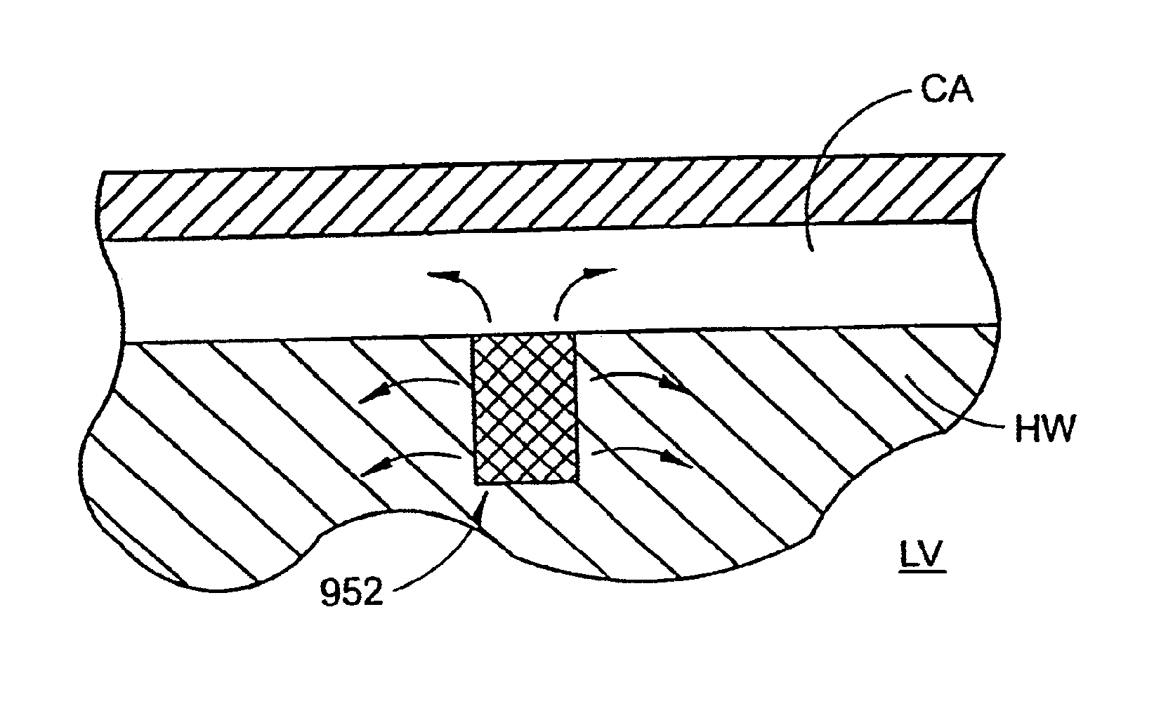
[0184]FIG. 37 is a cutaway schematic representation of the shunt device 412′ depicted in FIG. 34 mounted within the patient, with the conduit end resident within the myocardium HW. The coronary artery CA and the bypass graft 414 are shown to be placed in fluid com...

embodiment 1716

[0218]FIG. 52 illustrates an alternate embodiment 1716 with a distal extension 1720 extending both distally in the coronary artery CA as well as proximally. Thus, the distal portion 1720 of the conduit 1716 has a T-like configuration. As shown in FIG. 52, this T-like distal portion 1720 of the conduit 1716 may have a lattice construction such as the conduit 1690 shown in FIGS. 50 and 51. The main body 1724 of the conduit 1716 of FIG. 52 may be a smooth tubular structure, or may be of a lattice construction as shown in FIGS. 50 and 51.

[0219]The conduit 1730 of FIG. 53 has an articulating distal portion 1734 which may fold down either in a manner so as to either extend distally with respect to the coronary artery CA or proximally, as shown in FIG. 53. In this case, the distal extension 1734 of the conduit 1730 is preferably of a lattice construction made from a nitinol hypotube as discussed above. This distal portion 1734 is designed to collapse against the main body 1738 of the condu...


PUM


Abstract

A method of treating a heart may include providing an implant having a first end and a second end, placing the implant in a heart wall between a heart chamber and a blood vessel such that the first end of the implant is in flow communication with at least one of the geart chamber and the blood vessel, and delivering an angiogenesis factor in a time-relaease mannor to the heart wall proximate the implant.

Description

CROSS-REFERENCE TO RELATED APPLICATIONS[0001]This application is a continuation of application Ser. No. 09 / 534,038, filed Mar. 24, 2000, which is a continuation of application Ser. No. 09 / 369,039, filed Aug. 4, 1999, now abandoned, which is a continuation-in-part of application Ser. No. 09 / 016,485, filed Jan. 30, 1998, now abandoned, and a continuation-in-part of PCT Application No. PCT / US99 / 03484, filed internationally Feb. 17,1999, and which claims the benefit of U.S. Provisional Application Nos. 60 / 099,691, 60 / 099,720, and 60 / 099,767 each filed Sep. 10, 1998; and U.S. Provisional Application No. 60 / 104,397, filed Oct. 15, 1998, all of which are incorporated herein by reference.BACKGROUND OF THE INVENTION[0002]1. Field of the Invention[0003]This invention relates to an apparatus and method for implanting a conduit to allow communication of fluids from one portion of a patient's body to another; and, more particularly, to a blood flow conduit to allow communication from a heart cha...

Claims


Application Information

Patent Timeline
Patent Type & Authority Patents(United States)
IPC IPC(8): A61F13/00A61F11/00A61F2/00A61F2/06A61F2/04A61B17/03A61M5/00A61B17/08A61M37/00A61B5/00A61B5/0215A61B5/026A61B17/00A61B17/11A61F2/02A61F2/94A61MA61M25/00A61M27/00
CPCA61B5/0031A61B5/6862A61B5/6876A61F2/06A61F2/2493A61F2/915A61F2/94A61B5/0215A61B5/026A61B2017/00247A61B2017/1107A61B2018/00392A61F2/064A61F2002/91508A61F2002/91516A61F2002/91525A61F2002/91533A61F2002/91575A61F2250/0002A61F2250/0039A61F2250/0067A61F2220/0008A61F2220/0016A61B17/0057A61B17/11A61B17/3468A61M27/002A61B2017/00252A61B2017/00637A61B2017/00654A61B2017/1135A61F2002/8486
Inventor WILK, PETER J.
Owner HORIZON TECH FUNDING CO LLC
Why Eureka
Try Eureka