Intermittent mixer with low pressure drop

a technology of mixer and pressure drop, which is applied in the field of intermittent mixing, can solve the problems of insufficient cooling of flue gas passing the out-of-service sda, inconvenient use, and inconvenient use,

Inactive Publication Date: 2005-09-20
THE BABCOCK & WILCOX CO
View PDF22 Cites 84 Cited by
  • Summary
  • Abstract
  • Description
  • Claims
  • Application Information

AI Technical Summary

Benefits of technology

[0013]It is an object of the present invention to provide an apparatus in the form of a mixer which reduces the temperature of flue gas supplied to a fabric filter. Two or more spray dry absorbers are operable to cool flue gas. A housing of the mixer has first and second inlet passages for gas from the absorbers, an outlet passage for gas to the fabric filter, and a mixing passage. A set of damper vanes extends in the mixing passage and has a mixing position for mixing the flue gases from the inlet passages to supply mixed gas to the outlet passage at relatively high pressure drop but lower temperature if one of the absorbers in not operating. They have a non-mixing position for passage of gases without mixing, and at low pressure drop, when both absorbers are operating.
[0014]It is a further object of the invention to provide a method for reducing the temperature of flue gas supplied to a fabric filter from two spray dry absorbers when one of the absorbers is not operating to cool the gas passing therein.
[0015]It is a still further object of the invention to provide a method for mixing two gas streams to make the gas composition of the combined stream more uniform.

Problems solved by technology

A spray absorber may also malfunction.
During such upset periods the flue gas passing the out-of-service SDA will not be cooled sufficiently to pass to the following fabric filter structures for particle removal, since the high temperature of the gas would damage the fabric.
These bags, however, are more expensive and may not work as well.

Method used


Image

  • Intermittent mixer with low pressure drop
  • Intermittent mixer with low pressure drop
  • Intermittent mixer with low pressure drop

Examples


Embodiment Construction

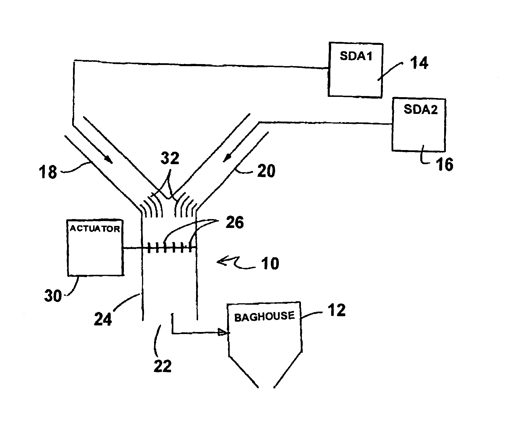
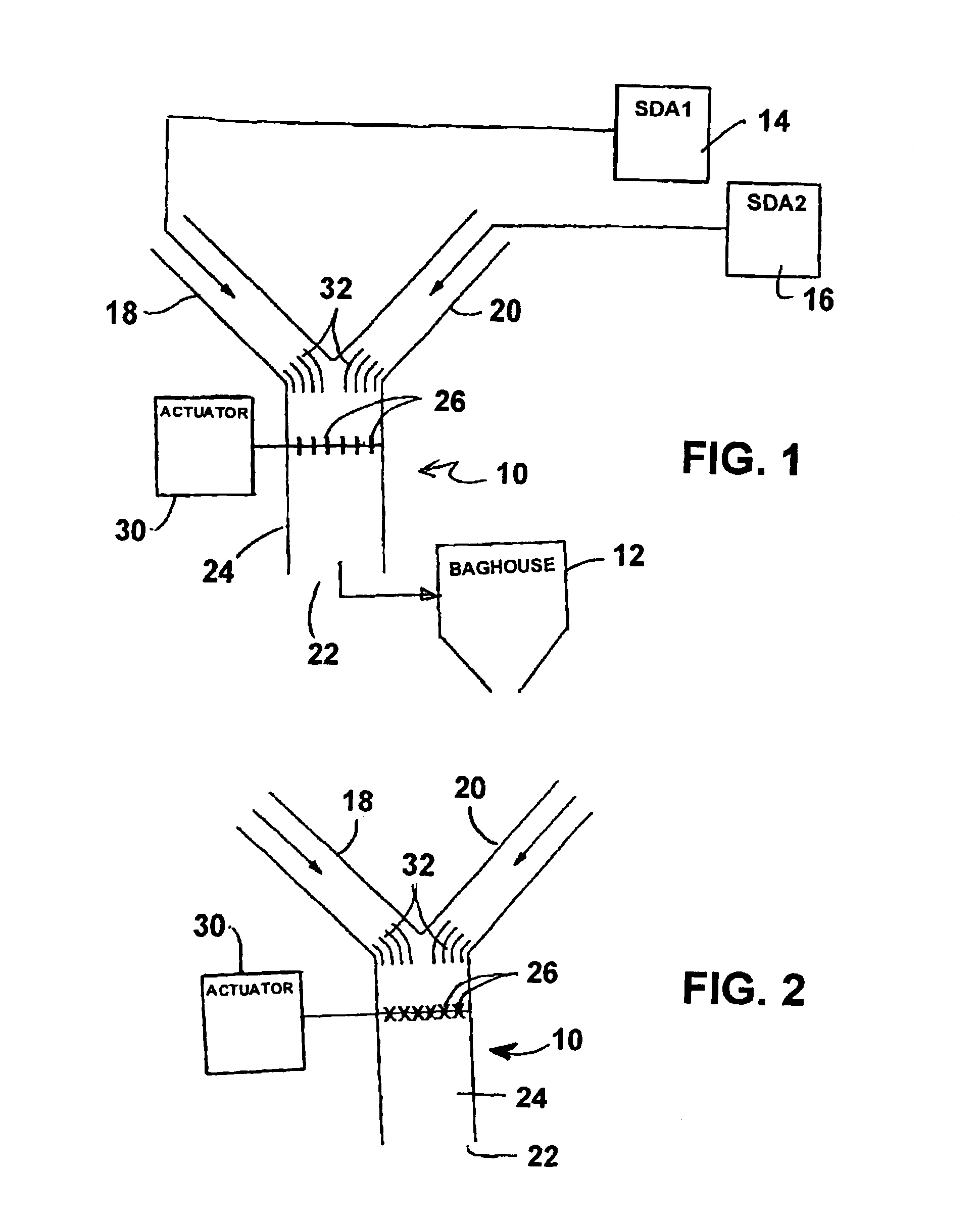
[0025]Referring now to the drawings, in which like reference numerals are used to refer to the same or similar elements, the invention is a mixer 10 in FIG. 1, for mixing two gas streams, e.g. for reducing overall temperature of flue gas supplied to a fabric filter such as a baghouse 12. Such filters containing fabric having a maximum temperature tolerance, e.g. about 250 degrees F. for lower-cost bags.

[0026]The flue gases come from at least two spray dry absorbers 14 and 16 which are each operable to cool flue gas passing therein in a known manner.

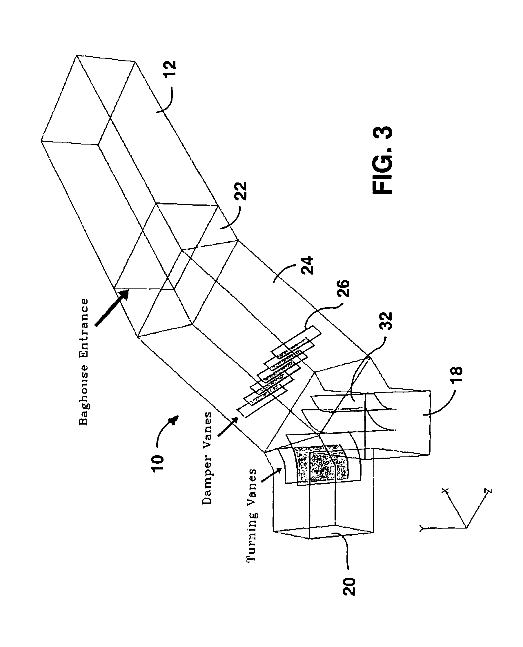
[0027]Mixer 10 comprises a housing having a first inlet passage 18 for flue gas from the first spray dry absorber 14, a second inlet passage 20 for flue gas from the second spray dry absorber 16, an outlet passage 22 for supplying flue gases from the first and second spray dry absorbers to the fabric filter or baghouse 12, and a mixing passage 24 between the inlet passages 18, 20 and the outlet passage 22.

[0028]A plurality of damper vanes...


PUM


Abstract

A thermal mixer reduces the temperature of flue gas supplied to a fabric filter. Two spray dry absorbers are operable to cool flue gas. A housing of the mixer has first and second inlet passages for gas from the absorbers, an outlet passage for gas to the fabric filter, and a mixing passage. A set of damper vanes extends in the mixing passage and has a mixing position for mixing the flue gases from the inlet passages to supply mixed gas to the outlet passage at relatively high pressure drop but lower temperature if one of the absorbers in not operating. They have a non-mixing position for passage of gases without mixing and at low pressure drop when both absorbers are operating. The invention can also be used to improve mixing of combined gas streams initially having different chemical compositions or amounts of particle loading.

Description

FIELD AND BACKGROUND OF INVENTION[0001]The present invention relates, in general, to intermittent mixing of two or more gas streams, and, in particular, to a new and useful apparatus for mixing relatively hot and cold flue gases with each other before they are supplied to a fabric filter during periods when the hot gas would be above the safe operating temperature of the fabric filter.[0002]Dry scrubbing is the principal alternative to wet scrubbing for removing SO2 from flue gas released by utility boilers. Dry scrubbing is sometimes referred to as spray absorption, spray drying or semi-wet scrubbing. It involves spraying a highly atomized slurry or aqueous solution of an alkaline reagent into the hot flue gas, thereby absorbing SO2 and adiabatically cooling the flue gas. Unlike a wet scrubber installation, a dry scrubber, or spray dryer absorber, is positioned before a dust collector, such as an electrostatic precipitator or fabric filter. A fabric filter, or baghouse, collects dr...

Claims


Application Information

Patent Timeline
Patent Type & Authority Patents(United States)
IPC IPC(8): B01D53/50B01F3/00B01F3/02B01F5/06F23J15/02B01F23/10
CPCB01D53/508B01F3/026B01F5/0611F23J15/025B01F2005/0625B01F2005/0636F23J2217/101F23J2219/60Y10S366/03Y10T137/87748Y10T137/0318Y10T137/2572Y10T137/2564Y10T137/87668Y10T137/87652Y10T137/8766B01F23/19B01F25/4311B01F25/4316B01F25/431971
Inventor SNYDER, ROBERT E.
Owner THE BABCOCK & WILCOX CO
Why Eureka
Try Eureka